I intend to make an 12V/1A SMPS power supply for the first time.

Irving

Joined Jan 30, 2016
5,068
Its possible, but depends on complexity of circuit. Basically join things together with some solid copper wire, say stripped out from some 1.5mm or 2.5mm T&E mains cable.; here's an example (not using perf board, but you'll get the idea...)

20260227_123345.jpg

Post your schematic...
 

BobTPH

Joined Jun 5, 2013
11,487
An SMPS is sensitive to layout. The chip manufacturers generally suggest a PCB layout that works. I would stick with that. You are asking for trouble using an an ad hoc construction.
 

dl324

Joined Mar 30, 2015
18,282
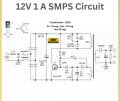
I want to escape PCB making in the first time because it should be more complicated process
for me as a beginner?
Absolutely possible. I used perfboards for prototyping for decades before I started making my own boards.

In some ways, it's easier because you can cross wires as much as you like.
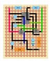
Is it possible to use these perfboards with no copper?
Examples using pad per hole board.
1773066074483.png1773066134104.png
1773066201272.pngsingleComparatorPWMComponent.jpg
6discreteFlipFlops.jpg6discreteFlipFlopsComponentSide.jpg4discreteFFBot.jpg4discreteFFComp.jpg

Note that in the last 2 examples, I wired on the non-pad side to avoid complications with shorting wiring to the pads.

However, I did use a schematic editor/PCB layout program to work out component placement and wiring. In the last example, I did the layout for a 4 flip flop circuit and modified on-the-fly to 6 to use up all of the board space.

Homemade board example:
powerFixBreadboard.jpgpowerfixBrd.jpg
 

schmitt trigger

Joined Jul 12, 2010
2,056
I always cheer for a new member to attempt a challenging project for the first time. It is a great learning opportunity.
However, I also wish for them to be able to finish their project successfully, to have the positive feedback required for someone to continue spending their time, effort and money pursuing their hobby.

To answer your question; although it can be done, it requires knowledge about layout and associated parasitic elements, which very likely you don’t possess.
Thus, if you would like to tackle the challenge, go ahead and proceed with your project. But don’t be discouraged if it doesn’t work, ok? You’ll at least learn a dozen things that you shouldn’t do.
 

Irving

Joined Jan 30, 2016
5,068
Most SMPS chips will work, just maybe not as effectively or as efficiently. With careful layout the parasitics may not be as bad as first imagined. Key is to keep the high current traces from controller to the inductor, and the ground return to the chip, as short as possible. What controller & other components are you planning to use? Post a schematic so we can advise further.
 

bertus

Joined Apr 5, 2008
22,909
Hello,

That looks like an oscillator with an extra winding for the 12 volts.
Keep in mind that the 12 volts output is not regulated.
There is no feedback from the 12 volts.

Bertus
 

Irving

Joined Jan 30, 2016
5,068
I intent to make this circuit.
You will be sadly very disappointed in the result. That's an ancient solution that has nothing going for it, and, being 'self-oscillating', has no guarantee it'll work. We had this conversation on your other thread back at the end of January, where you were advised to consider alternatives.

Personally I'd use the TNY27x chip which is available in a 7pin DIP case and their recommended layout is intended for through-hole parts and is easily adapted to a perf board solution with some copper sheet as a simple heat-sink. The component count is very similar. Attached is the TNY family and transformer data sheets. All parts, including the ready-made transformer, are available from Digikey, or you can wind your own to the same spec.

1773156238141.png


However, the one-off parts cost for building your own, of any design, is going to be much higher than buying a ready-made 12v/1A 'wall wart' or an open-frame device from the likes of AliExpress.
 

Attachments

Last edited:

Thread Starter

cmpx

Joined Oct 23, 2021
48
Absolutely possible. I used perfboards for prototyping for decades before I started making my own boards.

In some ways, it's easier because you can cross wires as much as you like.
I appreciate your reply and this procedure with perfboards would be sutable for me like a beginner.

I know that I should never use a breadboard for it because it is high voltage circuit and it would be dangerous.

But how I know the wires should not be too long because it makes negative EMI effect. There are critical components on high-voltage primary side like: diodes bridge, capacitors, power transistor and smps transformer. They should be close to each other as much as possible.

Electromagnetic Interference (EMI): The long, unshielded wires used in point-to-point turret wiring act as antennas, creating significant electrical noise and "ringing" that can interfere with the circuit's stability.
Turret boards are not sutable and I understand the reason.

How I said it is my first time and I must ensure all safety procedures for work with High Voltage. I ensured an incandescent bulb to connect entire my circuit in series with it for testing if the circuit works properly.

Should I use litz insulated wire for connected betwen componens or enamel magnet wire?
I would use litz insulated wire or enamel magnet wire that has Fi less than 1 mm.
 

dl324

Joined Mar 30, 2015
18,282
I know that I should never use a breadboard for it because it is high voltage circuit and it would be dangerous.
Your use of breadboard is ambiguous. Breadboarding can mean building a prototype, not necessarily solderless.
But how I know the wires should not be too long because it makes negative EMI effect. There are critical components on high-voltage primary side like: diodes bridge, capacitors, power transistor and smps transformer. They should be close to each other as much as possible.
The layout for those components isn't that critical. You could always just wire them up on perfboard using point-to-point wiring techniques.
 

Pyrex

Joined Feb 16, 2022
502
I intent to make this circuit.

I would not recommend this circuit diagram to you. Here is shown a flyback converter, self-exciting. This circuit diagram is very simplified . This circuit diagram is designed to produce a very cheap product, but it has its own cost. It will be difficult to adjust such a SMPS so that it works at least somewhat acceptably. I could bet that you will burn out a dozen transistors trying to tune such a converter.

I would recommend a forward converter, or a push-pull converter. Look for schematics online, there are many, I mean - functional ones.

Or do as advised to you in post #4 "for someone starting, why not try classical approach with transformer, rectifier and filter caps"
 

MisterBill2

Joined Jan 23, 2018
27,329
CERTAINLY building projects with bare perforated board can work. I have doneit quite a few times, because I am too cheap to buy a ready made PCB, or because there is no other method of assembling a circuit available, and mostly because I am aware that the circuit may need to be changed a bit. Building on a bare perforated board does require a fair amount of planning and thinking, though. It also demands adequate soldering skills, which is probably the most important requirement.
 
,,,,,,and mostly because I am aware that the circuit may need to be changed a bit. Building on a bare perforated board does require a fair amount of planning and thinking, though. ..........
That is "prototyping" in circuit engineering. Besides, working with KiCad, takes more time than DIYLC and ordering JLPCB is not cost effcient if you are making only one.
 

Irving

Joined Jan 30, 2016
5,068
............
That is "prototyping" in circuit engineering. Besides, working with KiCad, takes more time than DIYLC and ordering JLPCB is not cost effcient if you are making only one.
Which is why I suggested the TNY278 in post #11 as their recommended THT layout is perfect for a perf-board build... no deep thinking needed! Here I've just started transcribing the layout in the data sheet to perf-board to illustrate....


1773514691019.png
 
............
Which is why I suggested the TNY278 in post #11 as their recommended THT layout is perfect for a perf-board build... no deep thinking needed! Here I've just started transcribing the layout in the data sheet to perf-board to illustrate....


View attachment 364630
And I did not even watch a minute video on YT to figure it out! The interface is soooo user friendly! The trick that I use is I choose black for the jumpers that are to be soldered to the pads (under board) and different color to remember which ones are jumper wires over the board. Once done with routing, I press Alt+V to "mirror" the board. Then simply grab a piece of prefboard, look at the picture and solder the back traces without mounting any components, Then wash off the board the solder paste residues and you have a clean and compact board.
 
Top