 Facebook
 Google
 GitHub
 Linkedin
Hello everyone,
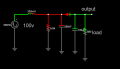
Is my first attempts for high power SMPS from mains.
I'm looking for a relatively symmetric trangle wave generator circuit to be used for PWM through an LM311 comparator and feedback reference voltage.
I found some challenges for a real implementation and i could use some suggestions:
- correct referencing : i see that in reality the reference voltage for the comparator must not go below the triangle, because the PWM pulse will go over 100% duty cycle, meaning if the circuit relies on switching for operation (like flyback or forward) will cause the primary coil of tranformer and primary switch to stay ON. (this is short circuit on the source through the main switch)
- power supply from mains. Since this would be a control circuit for a power supply, we can't have a power supply to build a power supply. We need to run this from mains after Full wave bridge. in my country we have 240V 50Hz, so i need to run this circuit from about 350V DC.
- is it worth investigating a similar triangle wave generator with only transistors ? or the shape will be much worse? i'm wondering about this, because we can choose 400V transistor versions and resolve the previous point issue.
Any comments appreciated !

")


