Smoker Circuit Design

Thread Starter

killivolt

Joined Jan 10, 2010
836
How about treating this chip loader like a windshield wiper? Auto-lock-out microswitch after 1 revolution and a short over-ride pulse to get it to start the next revolution.
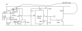
Thats where the Hall Effect comes in, after one revolution of the motor, the Hall Effect sensor will trip the 555 to start the delay. The field effect works like a momentary switch. During delay the 555 pulls the 2n222 down shutting off the LTE and release it after. I plan on putting this all together in a truth table and build a working circuit with all in place if I'm correct.

kv
 

Thread Starter

killivolt

Joined Jan 10, 2010
836
How about treating this chip loader like a windshield wiper? Auto-lock-out microswitch after 1 revolution and a short over-ride pulse to get it to start the next revolution.
But, I like your idea. Didn't know how they work, I like it.

kv
 

#12

Joined Nov 30, 2010
18,224
But, I like your idea. Didn't know how they work, I like it.

kv
That was me assuming everybody knows about windshield wipers.:rolleyes:
It's called a "parking" switch. As long as DC is applied, the motor runs, and it keeps running after the power is not applied...until it hits the parking switch. That's why your windshield wipers always stop at the bottom.
 

Thread Starter

killivolt

Joined Jan 10, 2010
836
That was me assuming everybody knows about windshield wipers.:rolleyes:
It's called a "parking" switch. As long as DC is applied, the motor runs, and it keeps running after the power is not applied...until it hits the parking switch. That's why your windshield wipers always stop at the bottom.
If my thought won't do the trick, then more tricks in the bag the better:)

kv
 

Thread Starter

killivolt

Joined Jan 10, 2010
836
Waiting for the LTE, LTR, and hall effect switches. Meanwhile, I dropped the 1 meg pot into the 555 diagram at 55k was 1 minute, then 555,000k 10 minutes, and 1 meg exactly 20 minutes on 2 separate testso_O

CD4020 is still in, regardless of the 555 test, I just wanted to show this guys circuit is true or false. I'll bread board CD4020 hopefully this weekend. CD4020 has more usefulness with combined times, as well as reliability over time.

What do you think? Time a bin burn rate until gone base that on a long count, then allow bin load or no load. This along with Shorter time, to allow for smoke and watchdogs on the Chimney, Thermostate for Temp.

kv:)
 
Last edited:

Thread Starter

killivolt

Joined Jan 10, 2010
836
I just put in a 10meg resistor which should delay for 3.3 hrs, I have a 1.5vdc clock running off pin 3. I had to drop the voltage down from 3.5 to 1.97 so it wouldn't double the speed of the clock.

I'll know by tomorrow if that worked, maybe it's possible the 555's wired monostable that it seems to work, not sure?

kv
 

Thread Starter

killivolt

Joined Jan 10, 2010
836
It worked, stopped right at 3 hrs. The test was done with a clock that run on a 1.5vdc battery regular clock face, a 555, plus the schematic in post #138 1000uF cap, 10meg resistor.

I got the CD4020 on a bread board with the 555 now just waiting for the LTE, LTR, Triac's, HallEffects.

kv
 

#12

Joined Nov 30, 2010
18,224
Are you counting time from zero volts on the capacitor to 2/3 Vcc? If so, that is a large error. It not only isn't a whole cycle of operation, it's the wrong starting point. However, I'm surprised that a 1000uf cap will ever charge up to 2/3 Vcc with 10 megs in series. That would be way less than 567 na leakage if you're using the 17 volt supply previously described.
 

cmartinez

Joined Jan 17, 2007
8,773
It worked, stopped right at 3 hrs. The test was done with a clock that run on a 1.5vdc battery regular clock face, a 555, plus the schematic in post #138 1000uF cap, 10meg resistor.
Did you physically test that setup? Or was it an LTspice simulation? ... #12's right, I'm surprised you got those results, and if you did, I'll be even more surprised if they remain consistent after a few weeks.
 

Thread Starter

killivolt

Joined Jan 10, 2010
836
Are you counting time from zero volts on the capacitor to 2/3 Vcc? If so, that is a large error. It not only isn't a whole cycle of operation, it's the wrong starting point. However, I'm surprised that a 1000uf cap will ever charge up to 2/3 Vcc with 10 megs in series. That would be way less than 567 na leakage if you're using the 17 volt supply previously described.
Only using a 5vdc 0-1.5amp supply on the bread board, in order to make the clock run I put an LED in Parallel on pin 3 but, it counted 3.3hrs. It's not exact, as you would want but, it's in the ballpark.

I was thinking I could take some video and alter it in fast motion but, don't want to go to the trouble, it's not exact if that's what your saying but it will delay long durations.

kv

Edit: To get a better more accurate time, I think making a video with the time linked to the video would be best to know down to the second.
 
Last edited:

Thread Starter

killivolt

Joined Jan 10, 2010
836
Did you physically test that setup? Or was it an LTspice simulation? ... #12's right, I'm surprised you got those results, and if you did, I'll be even more surprised if they remain consistent after a few weeks.
If you recall it will only do these delays and be reset by the rotation of the auger motor, not doing long time counts. Yes, I physically hooked a clock and covered the battery ends with electrical tape I attached leads + and - to the board clock, pin 3 hot and then to ground. The clock has second, minute, and hr hands. Based on the calculation of the fellows circuit in post # 138 55k and 1000uF results in 1 minute plus or minus 10 seconds, 555,000 and 1000uF results 10 minutes, and 1meg, 1000uF 20 minutes, 10 meg, 1000uF 3.3 hrs.

kv
 

Thread Starter

killivolt

Joined Jan 10, 2010
836
For the benefit of those who don't know the inner workings of the mighty 555, I have an animated example, it's helps me to see the gears and wheels at work. "The original animation was to fast, I made it slower"

The animation is not what I did, I'm triggering pin 2 with a switch not a capacitor.

If you want precision of long counts, @#12's circuit including the CD4020, ripple-carry binary counter/divider is the way to go.


Enjoy,

kv
 

#12

Joined Nov 30, 2010
18,224
That's really good! I always have to look up a datasheet to remember that the output is high while the voltage on the timing capacitor is increasing.
 

Thread Starter

killivolt

Joined Jan 10, 2010
836

#12

Joined Nov 30, 2010
18,224
So, how do I setup the 555 you have a line to pin 4 from pin 3 on the CD4020. Just run a jumper?
No, I inverted pin 3 of the CD4020 with a transistor to stop the 555.
You need to reset the CD4020 with the start switch.
"The counters are reset to the zero state by a logical 1 at the reset independent of clock."
Therefore, when you hit the reset button on the CD4020, all the outputs go low, the transistor shuts off, and the 10k resistor allows the 555 to run by bringing its reset pin high.
Are we both looking at the same drawing?
 

Attachments

Thread Starter

killivolt

Joined Jan 10, 2010
836
No, I inverted pin 3 of the CD4020 with a transistor to stop the 555.
You need to reset the CD4020 with the start switch.
"The counters are reset to the zero state by a logical 1 at the reset independent of clock."
Therefore, when you hit the reset button on the CD4020, all the outputs go low, the transistor shuts off, and the 10k resistor allows the 555 to run by bringing its reset pin high.
Are we both looking at the same drawing?
Thats what happened, I wired it wrong. All working correctly now.

Thanks again.

kv
 

Thread Starter

killivolt

Joined Jan 10, 2010
836
I've done several test's, this thing is amazing @#12, well done. I calculated 14 minutes with a 10k pot. I figure if I want day's 10meg would be 9.7 day's. Now all I need is to know how long till smoke happens. I need to make a test on the LTE and LTR, if that won't work, I might just try to burn an amount of chips and time that, then delay the auger to that time. I might also run my burner off one of the other pins or build another circuit to be on - off cycling the burner every 1 to 2 minutes, so the heat won't climb.

I'll still have the thermostat in there for safe Temps. Lots and Lots of testing to be done.

kv
 

#12

Joined Nov 30, 2010
18,224
I figure if I want day's 10meg would be 9.7 day's.
You're better off using larger film capacitors because low leakage...then start pushing the edge with high ohm resistors.
Today I re-fitted an antique amplifier. 80uf @ 450VDC.
After 2 hours the leakage current decreased to 84ua.
If I extrapolate this to 1000 uf @4.5V you would have 10 ua leakage, but you need to be at less than 1% of that for a reliable timer, and you can't reasonably let the timer capacitor "soak" while the leakage current decreases after it's been in the shed for 6 months. Yay, CD4020! That chip extends a 555 to hours without any worry about timing errors.
 

#12

Joined Nov 30, 2010
18,224
It looks to me like you have 3.75 minutes there and you're trying to run the smoke detector LED off the 555 timer reset pin, which won't work. The reset pin of a 555 chip will not provide current to run an LED.
Meanwhile you have a Hall Effect sensor trying to make the reset pin on the long delay chip go high, which restarts the long delay timer.
(That might be the right thing to do, depending on what exactly you're planning.)
You forgot to include the 38KHz timer and driver for the smoke detector and connected the smoke LED to the chip auger timer.
You also attached over 16 volts to a 15 volt chip (CD4020).

Please excuse the cursory nature of my inspection. I am up to my alligators in cash jobs right now.
 
Last edited:
Top