Facebook
 Google
 GitHub
 Linkedin
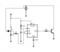
Hello I have a dc geared motor, about 6v and 500ma, and I want there to be a small delay in stopping it.
When the motor is on it goes through a SPST normally closed switch. When I open the switch to turn off the motor I would like about a 1-2second delay before the motor cuts off completely.
Could a large capacitor across the switch provide the necessary current to drive the motor for the brief amount of time? If so how large of a cap would it take?
I tried doing this with a 470uf capacitor I had laying around and it didn't seem to do anything.
Thanks for your help and (obviously) my electronic knowledge is limited.
Matt