sink and source currents of series 74LS TTL

Thread Starter

cruizerdog92

Joined May 7, 2013
10
Hey all,
I'm currently working on a project using logic gates to trigger LEDs, relays etc.

I am supposed to use series 74 TTL so im assuming that means 74LS opposed to 74HCT as its CMOS.

for my circuit i've only got leds feed off the gates and the rest off transistors due to the high current.

My question is what are the general sink and source currents of 74LS gates. I'll be using basic gates such as quad 2-input and, or gates and hex inverter.

I've got a basic understanding of the different between sink and source. source is getting voltage from gate at "1" and then earthing. while sink is seperate voltage and earthing at gate when its "0".

i've got mixed answers such as they source 15 - 25 mA and only sink 0.4 mA or that they sink up to 16mA but they can source only about 2mA

Looking at the 74LS datasheets i believe that sink current is Iol and source is Ioh. If datasheets are right that means 74LS can handle more sink current than source current. If so does that mean i should really be connecting my LEDs in sink instead of source?

Expert knowledge in this field would be much appreciated and thank you in advance

Cruizerdog
 

MrChips

Joined Oct 2, 2009
35,299
You are on the right track. All of the information you need is in the datasheet.

For 7400, 7404
IOH is -0.4mA
IOL is 16mA

For 74LS00, 74LS04
IOH is -0.4mA
IOL is 8mA

Yes, for maximum current you should use it as a sink.
 

Thread Starter

cruizerdog92

Joined May 7, 2013
10
Thanks for that Mr Chips.

0.4mA doesnt seem very high. That means i'll probably have to change my transistors as well then. I was planning to use 2n2222a.

the datasheet says that Ib at 15mA has a Vbe saturation voltage of 0.6v to 1.2v. does this mean i have to have a minumum of 15mA for it to work or is it saying that if i had 15mA the voltage must be between that value. Therfore could it work with a lower Ib but the saturation voltages would change.

or maybe its saying that the voltages must be between 0.6v and 1.2v and the current can vary.

sorry for the messy train of thought. trying my best to write my ideas down while making sense
 
Last edited:

MrChips

Joined Oct 2, 2009
35,299
IOH = 0.4mA is at the rated VOH = 3.4V.

If you are driving the base of a transistor, you can source 12mA @ 2.5V or 20mA @2V.

Hence you can drive the base of an NPN 2N2222A transistor with a base series resistor from 220Ω to 1kΩ and still get good results.
 

MrChips

Joined Oct 2, 2009
35,299
Just remember that this applies to driving the base of a transistor from a logic HIGH.
After 20mA @ 2V output, the logic level is no longer guaranteed to be logic HIGH. i.e don't attempt to tap off this output for a logic signal.
But your NPN transistor will still be turned on hard.
 

WBahn

Joined Mar 31, 2012
33,339
I just want to add that, from the beginning, you were asking the right questions and showing that you are thinking about what things mean and what they imply. Good job. You are doing just fine.
 

jomelavenido

Joined Jun 10, 2013
13
hello!!!

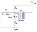
i am very confuse right now.. datasheets and every info i have gathered told me that LS TTL ics cannot drive LED.. but how come it works fine with 74LSXX even the LED is in series with a 220 ohm resistor to the ground..

for example, when the output is high for 74ls04 the led is on, though the datasheet is telling me that it can only source current for -0.4 mA but the multimeter tells me its 13.5mA.. arghhhh..!!!

someone help me please... :(
 

MrChips

Joined Oct 2, 2009
35,299
If you read the datasheets you will find that the -0.4mA source current is spec'd at a given VOH.
With heavier loads VOH is going to be lower. This is why it cannot be guaranteed to be a logic HI, i.e. don't use this output to feed another part of your logic circuit.

I am surprised that you are reading 13.5mA, not with a 220Ω resistor and an LED as load!
You must be shorting the output to GND with your ammeter.
 

WBahn

Joined Mar 31, 2012
33,339
Don't measure your current with the ammeter function of your multimeter. Get your circuit working with the output HI and the LED on. Have the LED connected between the gate output and the resistor and the resistor connected between the LED and ground. Then measure the voltage across the resistor and make a note of it. Then measure the voltage at the gate output relative to ground and make a note of it. Compute the current by dividing the first voltage by the value of the resistor.
 
i guess im wrong with the current 13.5 mA.. but im very sure that the circuit is working and the source current is more than enough to drive the led... i have measured the output voltage and its approximately 3V.. the led's drop voltage is approximately 2V so very obvious that the 220 ohms has the 1V right? therefore the current that is flowing is 1V/220ohms = 4.5mA.. that is enough to drive the led on...
 

MrChips

Joined Oct 2, 2009
35,299
I tested your circuit on a breadboard and I get 3 to 6mA depending on the specific LED, particularly its color. A blue LED will have a higher forward voltage and hence will result in a lower current.
 
hmmmm.. so what's with the -0.4mA high output current at 3V for LS TTL..? and an idea that it cannot drive LED? but infact in an actual implementation, -0.4mA is disregarded and hence 3V high output voltage is the only thing you need to compute for the actual current that flows through the load series with a resistor to the ground...

What can you conclude sir? for me, i think that the current is only -0.4mA when no load is connected from the output to the ground. but since a load of LED and a resistor is connected therefore a larger current is able to drive a led.. or any device that only requires less than 3V...
:)
 

WBahn

Joined Mar 31, 2012
33,339
MrChips explained this in post #10.

First thing you should do is tie all of the unused inputs either to ground or to Vcc (preferably through a resistor, but that's not critical). Get in the habit of doing this.

The data sheet says that the the maximum IOH is -0.4mA (the negative sign is an artifact that all currents are positive if going INTO the pin, so this actually means a current of 0.4mA coming out of the pin). But, at MrChips explained, what this is saying is that the manufacturer of the device is merely asserting that as long as you draw no more than that current, that the output voltage will exceed the VOHmin of 2.7V over the entire temperature range of operations even when VCC is at it's minimum and the input voltage to that gate is at its maximum (since this is an inverter) of 0.8V.

It does NOT say that the device CANNOT produce more current that 0.4mA or that the output WILL be less than VOHmin if you do. The manufacturer simply doesn't guarantee that this won't be the case.

Think of it like a bench seat that is rated to deflect downward no more than 3" at the middle as long as the person sitting on it is less than 300lb. You buy three of these and put them side by side and find three people that are 250lb, 350lb, and 450lb to sit on them. If the one with the 450lb person deflects only 2", that's great and that meets the guarantee. But if the one with the 250lb person deflects 4", that violates the guarantee. But if the one that has the 350lb personn also deflects 4", that's not in violation.

The bench maker is NOT saying that the bench WILL deflect more than 3" if the person exceeds 300lb, they are only saying that it WILL NOT deflect more than 3" if the person DOESN"T exceed 300lb.

Do you see the difference?
 

absf

Joined Dec 29, 2010
1,968
I did some simulations and found that the current between the output of LS04 to the input of next LS04 is -0.42mA during logic LOW.

When the output of the first LS04 is HIGH, the current is +0.09mA.

Is that a coincidence?

Allen
 

Attachments

Last edited:

absf

Joined Dec 29, 2010
1,968
hmmmm.. so what's with the -0.4mA high output current at 3V for LS TTL..? and an idea that it cannot drive LED? but infact in an actual implementation, -0.4mA is disregarded and hence 3V high output voltage is the only thing you need to compute for the actual current that flows through the load series with a resistor to the ground...

What can you conclude sir? for me, i think that the current is only -0.4mA when no load is connected from the output to the ground. but since a load of LED and a resistor is connected therefore a larger current is able to drive a led.. or any device that only requires less than 3V...
:)
I just found the pdf file by Texas Instruments titled "Understanding and Interpreting Standard-Logic Data Sheets"

The explanation is the same as what WBahn has given...

IOH High-Level Output Current

JEDEC – The current into the output terminal with input conditions applied that, according to the
product specification, establishes a high level at the output.

TI – The current into an output with input conditions applied that, according to the product
specification, establishes a high level at the output.

TI data sheets specify currents flowing out of a device as a negative value. IOH max is used as a
test condition for VOH. See VOH testing for further details.

Logic output drivers have a maximum current drive capability that they can source and still be
able to sustain a valid logic-high level. In a static dc state, where current is drawn continuously from the output, because CMOS drivers operate in the linear region, their behavior is somewhat like a low-impedance resistor and increases in voltage potential (i.e., decreases the VOH level) as the increasing current is sourced out of the output pin during a VOH test.
Consequently, a TI logic device operates with a high-level output current that is above the recommended operating range (but below the absolute maximum rating), but TI does NOT represent that the device can sustain the specified VOH level or that the device will operate without any reliability concerns.
VOH High-Level Output Voltage

JEDEC – The voltage level at an output terminal with input conditions applied that, according to
the product specification, will establish a high level at the output.

TI – The voltage level at an output terminal with input conditions applied that, according to the
product specification, establishes a high level at the output.

VOH is tested with input conditions that should cause the output under test to be at a high-level
voltage. The output then is forced to source the required current, as defined in the data sheet,
and the output voltage is measured. The test is passed if the voltage is greater than VOH min.
The input voltage levels used to precondition the device are VIL max and VIH min, as defined in
the recommended operating conditions. See IOH high-level output current for further information.

Helpful Hint:

Inclusion of a VOH specification with a test condition of IOH = –100 µA is done primarily to
indicate that the device has CMOS outputs instead of bipolar (npn or pnp) drivers. Bipolar output
transistors typically are not able to swing the output voltages all the way to the power-supply rail or ground rail, even under no-load or lightly loaded conditions. If a device has bipolar outputs, this test condition would not apply and is not included in the data sheet. If you see this specification, you can safely assume the outputs to be of CMOS construction.
Allen
 
Last edited:
Top