Single supply opamp biasing, filter noise

Thread Starter

hrs

Joined Jun 13, 2014
397
Hi,

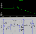
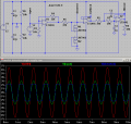
I'm looking into how guitar distortion pedals work and came up with the attached circuit. Assuming the guitar output is around 1 to 2 volts the signal needs a little bit of amplification from U1. The mosfets clip the signal. U3 buffers the signal because otherwise the filter at U2 will load the mosfets too much. Actually that's pure conjecture, but without the buffer there is no more or very little distortion. So that's what the circuit tries to do. I would probably use a TL074 but LTSpice doesnt have it. The input amplifier is inverting for no particular reason because I don't know when you would use one or the other.

Is the simple voltage divider an acceptable way of replacing a split supply or are there better ways?

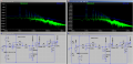
To me it looks like the filter is not working at all. Instead it just raises the noise floor. I get the same result with a simple passive RC filter. Is this how filters work or am I doing it wrong?

As always I'm also interested in comments about thing I didn't think to ask.
 

Attachments

#12

Joined Nov 30, 2010
18,224
1) a 2 resistor supply splitter avoids using 2 batteries to get a bipolar function of the amplifiers.
2) it works because you only need microamps to bias an op-amp.
3)A TL07x or a TL08x needs a lot more supply voltage to function correctly in this circuit. I used the TL082 with a +/- 15V supply.
4) I think this circuit sucks as a distortion generator, and I think you proved it with your simulations. My Les Paul can do 6 volts p-p if you hammer it. Try a higher input voltage.
5) the inverting form places a 10k load on the guitar signal, which I believe is a mistake. I have had wonderful results by increasing the input impedance so it doesn't load down the guitar signal. Consider the "usual" 100k to 500k volume controls in guitars. They don't work well with a 10k load.
 

OBW0549

Joined Mar 2, 2015
3,566
Is the simple voltage divider an acceptable way of replacing a split supply or are there better ways?
There are times when you can get away with a simple resistive voltage divider as a "supply splitter", and times when you can't (such as when the artificial "ground" created is called upon to sink or source substantial amounts of current from someplace or other).

Your circuit kind of falls in between those two cases: when no clipping is taking place, I suspect everything will be fine. However, when your clipping circuit M1/M2 comes into play at high signal levels, the current flowing through M1 & M2 goes into "ground" which is actually the junction of R6 and R7. Since this point in the circuit has a non-zero impedance relative to what a true ground would be (specifically, 2.35 kΩ), that current will cause the voltage at the R6/R7 junction to go up and down. Capacitor C1 in your output filter circuit is also connected to this point, so that voltage fluctuation at R6/R7 will get coupled through C1 to the output of your filter.

What that will do to the acoustics of this gadget I cannot say; but if you want to make the circuit act more like it would if you had a real split supply, just connect a 470 μF capacitor across R6 and another one across R7. That will lower the impedance of your artificial ground to the point where it's negligible at audio frequencies.

Also, I concur with #12 about supply voltage: I'm not too confident that a TL074 would be very happy with just 9 volts total supply voltage. It might function, but it won't have very much input or output voltage range since it's not a rail-to-rail I/O opamp.
 

#12

Joined Nov 30, 2010
18,224
the current flowing through M1 & M2 goes into "ground" which is actually the junction of R6 and R7.
Interesting point. The feedback through the middle voltage point will cause a positive feedback in all conditions. I consider this another reason to make the first stage non-inverting. You get a higher input impedance and any feedback to the center point will cause negative feedback, thus suppressing the interference. Then, add a good filter capacitor at the center point to suppress the feedback effects to nearly zero.

You can raise the resistance of the voltage divider to (calculated) 11 million ohms and thus reduce wasted battery power in that circuit. A capacitor to ground will keep this high impedance from being susceptible to random noise pickup. Raising to 11 million ohms will cause a startup delay when you consider the filter capacitor, so you will want to reduce that resistance to get the RC time constant down to a tenth of a second or less.
 

Thread Starter

hrs

Joined Jun 13, 2014
397
Hmm, I failed to consider the supply voltage required by the opamp. Maybe an NE5532 would be better. On the other hand some more supply voltage headroom would probably be good to get more clipping.

4) I think this circuit sucks as a distortion generator, and I think you proved it with your simulations. My Les Paul can do 6 volts p-p if you hammer it. Try a higher input voltage.
If/when I'm going to make this I would put a rheostat in place of R4 to compensate as needed for the guitar output. Why do you think it sucks? Is it because the higher harmonics quickly drop of in dB? A 15V supply and more gain fixes this to some extend.
I found this page that has some ideas for clipping circuits. I would make my distortion widget such that I can easily swap out the clipping circuit for experimentation. Do you have any clipping circuit that you would recommend?

What do you folks think about the filter? While a flat noise floor is probably less disturbing I had expected the high frequency content to actually be attenuated instead of being drowned in noise.
 

Attachments

#12

Joined Nov 30, 2010
18,224
Why do you think it sucks?
1) Because you posted the wave form and the tops of the waves look normal and 2) you said,
without the buffer there is no more or very little distortion.
Then there is the idea that when M1 starts to turn on (positive going voltage) M2 receives a negative bias and it was already off with Vgs = 0
How you gonna get any current through M2 when it's biased off?

Oh, I get it...the body diode comes on at 0.6 volts.
 
Last edited:

Thread Starter

hrs

Joined Jun 13, 2014
397
1) Because you posted the wave form and the tops of the waves look normal
Well actually it's the Fourier transform of the output for a 1 kHz input sine wave. You can see the uneven harmonics at 3 kHz, 5 kHz etc. I've attached a screenshot with the distorted waveform in it.

Then there is the idea that when M1 starts to turn on (positive going voltage) M2 receives a negative bias and it was already off with Vgs = 0
How you gonna get any current through M2 when it's biased off?
To be honest I don't know. I just grabbed it from here, the second one on the page:
http://www.muzique.com/lab/zenmos.htm
 

Attachments

Thread Starter

hrs

Joined Jun 13, 2014
397
I have one of those cases too but it weighs a ton! I'm not expecting a few diodes to do much better than a tube amp, I just thought it might be a fun experiment. Incidently when stiking a full chord I measured my guitars outputs at around 2, 3 and 4V respectively, though this is at the bridge pick-up where the string excursion is less than at the neck.

After some more consideration and better selection of R and C values it appears that the filter does roll of the higher harmonic peaks. But why does it add about 30 dB of noise to the filtered signal? Or am I misinterpreting the plots?
 

Attachments

#12

Joined Nov 30, 2010
18,224

Attachments

Top