Facebook
 Google
 GitHub
 Linkedin
hello,
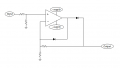
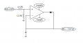
I have a single supply(3.3v) available in my circuit. I have an ac input current coming in the circuit ranging from 0 to 350 mA. I have a burden resistor of 10ohms,2 Watt connected across the ac input. Across burden resistor ,I get an equivalent vrms. I need an ac to dc conversion circuit to convert this vrms into dc voltage using single supply opamp. Please do not suggest a diode. I have designed a circuit using opamp and a bulk capacitor but it is taking time to smoothen the dc voltage. The ac input current coming to the circuit has to be detected within 100ms but this circuit needs the input to stay for more than 200 ms. can you suugest some alternative circuit solution.
I have a single supply(3.3v) available in my circuit. I have an ac input current coming in the circuit ranging from 0 to 350 mA. I have a burden resistor of 10ohms,2 Watt connected across the ac input. Across burden resistor ,I get an equivalent vrms. I need an ac to dc conversion circuit to convert this vrms into dc voltage using single supply opamp. Please do not suggest a diode. I have designed a circuit using opamp and a bulk capacitor but it is taking time to smoothen the dc voltage. The ac input current coming to the circuit has to be detected within 100ms but this circuit needs the input to stay for more than 200 ms. can you suugest some alternative circuit solution.