4-20ma to 0-3.3V conversion using Rail to rail Opamp ..#2

Thread Starter

HARDWARE TECHIE

Joined Dec 24, 2024
14
I am trying to convert 4-20 mA current loop signal to 0-3.3/0-3 V output for my 10 bit ADC IC that is connected to a Raspberry pi 3B+.
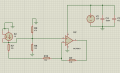
Schematic:

4-20ma to 0-3.3v

The input sensor is a 12 V loop powered 4-20 mA output humidity sensor. The op-amp is an MCP6002 rail-to-rail. The output of the op-amp is connected to a 10 bit ADC-MCP3008 (SPI enabled connected to RPi.)

The output voltage only varies from 0.6 to 2 V and I don't know where exactly the voltage drops.

The circuit works fine if I read the voltage using only a 150 Ω resistor (0-3 V.)

I can't understand what's wrong in this circuit.


Prior answers related to this question didn't give the solution. Please help me to find a reliable solution.
I also have same problem to convert 4-20ma into 0-3.3v but i am connecting it to stm32 and i want 0.1mv prescision so how can i get that result


Mod: link to old thread.
https://forum.allaboutcircuits.com/...-using-rail-to-rail-opamp.194166/post-1826317
 

ericgibbs

Joined Jan 29, 2010
21,390
Hi HT,
I guess you know, a 10 Bit ADC is only 1023 Counts?
So that is 2.9mV/Count resolution.

What is the maximum count of your ST32?
E

Checking, I see a 12Bit ADC for the ST32
EG57_ 2524.png
 

Jerry-Hat-Trick

Joined Aug 31, 2022
776
For 0.1mV resolution you need a 15 bit A/D converter, maybe a TC850 from Microchip. But I do wonder why you are looking for such high precision and whether the reading will be dominated by noise? Maybe oversampling with the 12 bit A/D would suffice?
 

Thread Starter

HARDWARE TECHIE

Joined Dec 24, 2024
14
For 0.1mV resolution you need a 15 bit A/D converter, maybe a TC850 from Microchip. But I do wonder why you are looking for such high precision and whether the reading will be dominated by noise? Maybe oversampling with the 12 bit A/D would suffice?
Thnks for the reply i know that stm32 has 12 bit adc and i am aware of it. My aim is to convert the 4-20ma or 0-20ma analog signal to the voltage level of adc of stm32. I want that much precision because i want to see the changes of every 0.1mv and i want that much precision with the help of op amp so can you please guide me about that how can i get that much precision.
 

Thread Starter

HARDWARE TECHIE

Joined Dec 24, 2024
14
Also i want to say that if we direct give 3.3v to opamp so we don't need voltage follower circuit am i right or wrong? if wrong please tell me
 

ericgibbs

Joined Jan 29, 2010
21,390
I want that much precision because i want to see the changes of every 0.1mv and i want that much precision with the help of op amp
Thnks for your information but if i want to make this happen without the use of potentiometer how is this gonna make it?
Hi HT,
You require 0.1mV precision, consider the tolerance values of the components you are using.
I would say even using all 0.1% tolerance you will not get a precise 0mV through +3.3V for a 4mA to 20mA drive input.
You need some method of trimming the vr Offset Voltage, also some way of trimming the Gain/Slope of the OPA, the 500R pot.

Also i want to say that if we direct give 3.3v to opamp so we don't need voltage follower circuit am i right or wrong? if wrong please tell me
The vr Offset voltage requires a stable, low output impedance source.

Your target of 0.1mV for the I2V >> ADC project requires a stable design.

E
 

Thread Starter

HARDWARE TECHIE

Joined Dec 24, 2024
14
Mcp6002 has input offset voltage around 4.5mv but in my information for 0.1mv precision input offset voltage have to low as 100uv around so can you suggest the op amp whose offset voltage is near to 100uv.
 

Thread Starter

HARDWARE TECHIE

Joined Dec 24, 2024
14
You need some method of trimming the vr Offset Voltage, also some way of trimming the Gain/Slope of the OPA, the 500R pot.


The vr Offset voltage requires a stable, low output impedance source.

Your target of 0.1mV for the I2V >> ADC project requires a stable design.

E
So you want to say that for my need of 0.1mv precision i have to trim the Vr offset voltage for stable design but with this triming method can i get this Vr offset voltage near to uv range if i am wrong please guide me
 

Thread Starter

HARDWARE TECHIE

Joined Dec 24, 2024
14
You need some method of trimming the vr Offset Voltage, also some way of trimming the Gain/Slope of the OPA, the 500R pot.


The vr Offset voltage requires a stable, low output impedance source.

Your target of 0.1mV for the I2V >> ADC project requires a stable design.

E
So you want to say that for my need of 0.1mv precision i have to trim the Vr offset voltage for stable design but with this triming method can i get this Vr offset voltage near to uv range for 0.1mv precision
 

Thread Starter

HARDWARE TECHIE

Joined Dec 24, 2024
14
Do you need an absolute accuracy of 0.1mV or just a precision (difference between measurements) of 0.1mV?
Such accuracy is much harder to do than precision, since precision is not affected by a fixed offset voltage.
As we know stm32's adc has 0.8mv resolution i want that after converting 0/4-20ma to 0-3.3v it give me 0.1mv precision as i want to see changes at every 0.1mv and from above circuit is there any need or modification on that circuit to achieve my goal?
 
Top