Facebook
 Google
 GitHub
 Linkedin

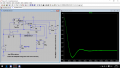
For that to happen you need to connect the clock output to one input of an added 2-input OR gate, and an added (new) zero-current comparator signal to the other OR gate input, with the OR output going to the FF set input so that either signal will turn the switch ON.6. Put in a clock frequency that controls when the switch turns on. (I assumed that, Tperiod is basically the clock frequency and Ton determined how long the switch would stay on for V3 in the same circuit of post #28)
7. If the current through the inductor reaches 0, or if a clock pulse is detected, turn the switch on. (Since the clock frequency is relatively high, I don't think that the current will have time to actually reach 0, but just in case, I wanted to add it as a condition)
Simulating a buck-boost converter in LTspice
- Thread starter vooper
- Start date