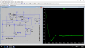
Simulating a buck-boost converter in LTspice

crutschow

Joined Mar 14, 2008
38,668
6. Put in a clock frequency that controls when the switch turns on. (I assumed that, Tperiod is basically the clock frequency and Ton determined how long the switch would stay on for V3 in the same circuit of post #28)
7. If the current through the inductor reaches 0, or if a clock pulse is detected, turn the switch on. (Since the clock frequency is relatively high, I don't think that the current will have time to actually reach 0, but just in case, I wanted to add it as a condition)
For that to happen you need to connect the clock output to one input of an added 2-input OR gate, and an added (new) zero-current comparator signal to the other OR gate input, with the OR output going to the FF set input so that either signal will turn the switch ON.
 

Thread Starter

vooper

Joined Dec 2, 2016
23
Would I have been wrong to think that, instead of putting the clock in the R position of the flip flop and put it into the S position, it would have sent a pulse to the switch making it turn ON?
 

crutschow

Joined Mar 14, 2008
38,668
Would I have been wrong to think that, instead of putting the clock in the R position of the flip flop and put it into the S position, it would have sent a pulse to the switch making it turn ON?
That would make the switch turn on and off with the clock pulse.
That makes no sense.
 

Thread Starter

vooper

Joined Dec 2, 2016
23
After breaking down the parts, I don't seem to understand how the flip-flop really works with the switch...
Am I just not connecting wires correctly, or does it seem that I just don't grasp the fundamentals of both components?

Removing the buffers and resistors for the current-voltage changing circuit seems to work fine, but there's still probably something wrong with it. Choosing the right op amp to use seemed to be a very big key part, where I think I chose a decent one, but it probably isn't optimal and I would like to ask for suggestions on this as well.
 

Attachments

Thread Starter

vooper

Joined Dec 2, 2016
23
I forgot to look at the english wiki page, and it indeed has much more information.

But what was confusing me was, I thought that the waveform at "out" would resemble the same type of waveform of Q in the flip-flop.
It didn't seem to work out well with a second pulse source either?
 

Attachments

crutschow

Joined Mar 14, 2008
38,668
But what was confusing me was, I thought that the waveform at "out" would resemble the same type of waveform of Q in the flip-flop.
Your confusion is confusing me. :confused:
When I simulate the circuit, the "out" waveform with an RLoad looks exactly like the Q output.
 

Thread Starter

vooper

Joined Dec 2, 2016
23
See new file:
Thank you Bordodynov.
Would you mind explaining the reason why a resistor is needed in parallel?
Is it because all circuits have that sort of load in order to properly output something?

As to reply to, crutschow, for me it seemed to output just a single line of 1V output with no dipping.
 

Thread Starter

vooper

Joined Dec 2, 2016
23
Without an output load, there's nothing to pull the output voltage to 0V so the output voltage just floats.
Ohh thank you, so I needed a ground so that there was a 0V reference point?

I was also thinking about changing the switching rule from, instead of having an upper reference voltage to having a lower reference voltage. So instead of having to worry about when the current reaches 0 and having the switch turn on, I would have it make the switch turn on when the reference current is reached. Then when a clock input is detected the switch will be turned off.
I wouldn't need to really change around many things in the "revisedbuckboost" circuit in post 26 would I?
 

Thread Starter

vooper

Joined Dec 2, 2016
23
Would what I had not just follow the lower threshold rule?

Have the switch be closed first so that the inductor can charge. Then when there's a clock pulse the switch opens until the current reaches the lower reference point. Then that process just keeps repeating.
 

Attachments

Thread Starter

vooper

Joined Dec 2, 2016
23
So I tried to think about it a bit, and tried a simplified approach to see if anything would change. If I assumed that CR was much greater than the clock frequency, so that the output could theoretically be thought of as a simple voltage source.

Pretty much the same thing happens where the simulation just takes forever, and it doesn't seem to work properly. Am I just doing something wrong that makes the simulation such a long time? Or does it just simply take forever due to a non conventional type of simulation?
 

Attachments

Thread Starter

vooper

Joined Dec 2, 2016
23
Really thankful for an actually working simulation result.

Though to try and explain a bit more of what I have been trying to achieve, I will attach a little pdf file (originally made in powerpoint, so that explains the layout).
Yes, I realize making the assumption of RC>>T isn't really something that should be done.
But I want to recreate the waveforms like when b < a. (the waveforms don't start at time=0s, but when a set amount of time has passed)
The bifurcation diagram is there to just show when chaotic properties should be seen.
 

Attachments

Top