 Facebook
 Google
 GitHub
 Linkedin
Hi all and thanks in advance for any help
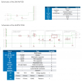
I plan to build circuits based on the attached but the fundamental difference being my input voltage will be 12v and not 24v. Basically I need to know what changes I should make to make sure I don't run into any problems.
I believe R1 and R2 of the "SUPPLY PCB" would need to be changed but what to exactly? And what type of diode/rating should they be?
Also wondering about the diode on the "IN PCB", I plan to make multiple supply PCB's all powered from the 1 in PCB and total output current on the 9v outputs could be anywhere between 2A and 6A
From my limited electrical knowledge I would assume the rest will be ok as it?
Thanks again
EDIT: I will be using a 7809 for 9v output
Attachments
-
 280.6 KB Views: 24
Last edited:


