Facebook
 Google
 GitHub
 Linkedin
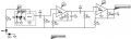
Hi, if I am to test for the output waveform of the OPT101 using an oscilloscope, do I need proper biasing on the circuit or I could simply supply the IC using a power supply? I have tried the basic connections of the OPT101 and I powered it up by 5-10Vdc with1.5A but I got no luck in seeing its waveform in the oscilloscope.
Moderator's Note:
Please don't hijack other member's thread, now you have your own.
This thread was split from --
OPT101 Photodiode Transimpedance Amp circuit.
http://forum.allaboutcircuits.com/t...ansimpedance-amp-circuit.108024/#post-1091451
Moderator's Note:
Please don't hijack other member's thread, now you have your own.
This thread was split from --
OPT101 Photodiode Transimpedance Amp circuit.
http://forum.allaboutcircuits.com/t...ansimpedance-amp-circuit.108024/#post-1091451
 .
.