How can I convert this board to run off an AC/DC adapter simply?

Thread Starter

popfresk

Joined Sep 14, 2024
9
Hello,

Perhaps this is too simple of a question but I am a complete amateur when it comes to questions like this. But it's something I'd like to learn more about and understand better.

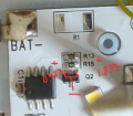
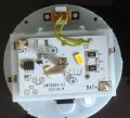
This device (photo attached) has 4 LEDs (two on the stick out of focus in the photo) that run off 3 AAA batteries. There is a mechanical switch at the top of the photo labeled S2. It has a built in timer that turns off the light after 1 hr appx. (S1?)

There are two things I'd like to do:
1. Remove or circumvent the 1 hr timer, so that the mechanical switch (or a new mechanical switch, don't care really) is the only thing that controls whether the diodes are on or off.
2. Add new wires that run to an AC/DC adapter and power it off that rather than batteries.

So, mainly I am worried that whatever adapter I use will somehow burn out the LEDs sooner than they would normally, so I don't really know what mA to pick (for voltage I would pick something close to 4.5 V or below). The reason for this is I see a lot of resistors on the board, so I am thinking if I somehow avoid those by just wiring the adapter to the diodes (which I think are just in series..?) directly, it won't work right.

My knowledge level of electronics is very simple and I haven't dealt with them since college so it's been a while. I only remember the basic stuff (P=IV.. V=IR.. etc), so please keep your explanations simple!
 

Attachments

LowQCab

Joined Nov 6, 2012
5,101
A 5-Volt Wallwart-Power-supply, and a single series-connected-Diode,
can directly replace the 3-Alkaline-Cells with no other changes.
Just make sure to test and verify the polarity with a Meter.

A Computer-Repair-Shop, or a Thrift-Store like "Good-Will", will have a big box full of them for ~$1.oo each.
.
.
.
 

Thread Starter

popfresk

Joined Sep 14, 2024
9
Thanks for your reply. I really want to maintain the geometry of the current diodes if possible, so that's why I wanted to put the AC/DC adapter wires directly onto the existing board if possible. The current provided on the 5V power supply won't matter really? Am I worrying more about the existing resistance on the board than I have to? I just don't want to burn out the diodes or heavily reduce their lifespan.
 

sghioto

Joined Dec 31, 2017
8,633
1. Remove or circumvent the 1 hr timer, so that the mechanical switch (or a new mechanical switch, don't care really) is the only thing that controls whether the diodes are on or off.
Interesting, I see a place on that circuit board that shows a place for another switch marked S1 with ON-OFF marked above it.
Might try moving the wires from S2 to S1.
 

SamR

Joined Mar 19, 2019
5,470
Load current is NOT determined by what the power supply is rated as capable of providing as current. The LOAD determines how much current is drawn FROM the power supply. As long as the power supply is able to supply that load current and more you are good. When more current than the power supply is capable of is demanded by the load, the voltage of the supply starts dropping to supply the current and the power supply is overloaded and is hopefully fuse protected or it will burn out... I=V/R with I being what current you want for your LED, V being the voltage provided by the power supply, and R chosen by you to provide the current needed for your LED. So it becomes R = V/I to specify your current limiting resistor for the LED.
 
Last edited:

Thread Starter

popfresk

Joined Sep 14, 2024
9
Interesting, I see a place on that circuit board that shows a place for another switch marked S1 with ON-OFF marked above it.
Might try moving the wires from S2 to S1.
I was thinking something like this might work. So you think if I run the switch over there it will circumvent whatever the rest of the board does to create the 1 hr. auto shut off?
 

Thread Starter

popfresk

Joined Sep 14, 2024
9
I think so.
So, I ordered my soldering stuff, and I just tried it, and it didn't work..
It turned on, but it still turns off after about an hour.

One thing I tested, is that when the switch is on, if I place a wire connecting the On/Off spots together it switches the lights off. Tapping it again turns it on again.

Something I noticed, is the Q2 on the board refers to a transistor. I did a bit of googling and transistors work like switches. When the physical switch is on and I tap the on/off to make it turn off, if I jumper either side of the transistor tops to the bottom side of the transistor, it turns on again.

I won't pretend I know much but perhaps the transistor's state is being swapped by the rest of the components so that not enough voltage is present to actually turn on the diodes?
 

sghioto

Joined Dec 31, 2017
8,633
Do you have a multi meter to get some voltage readings?
I believe there is a way to bypass the delay feature involving Q2
 
Last edited:

Thread Starter

popfresk

Joined Sep 14, 2024
9
Do you have a multi meter to get some voltage readings?
I believe there is a way to bypass the delay feature involving Q2
I do, I also sort of read up on how to identify the different terminals of the transistor, but I don't really understand how it works.
 

Thread Starter

popfresk

Joined Sep 14, 2024
9
Do you have time now to get some readings?
So I don't know the units that the diode setting gives, but this is what the multimeter gave: 0.433 V bottom to top left, 1.833 V bottom to top right.. so the top right is the emitter, the top left is the collector, and the bottom is the base?
 

Attachments

BobTPH

Joined Jun 5, 2013
11,463
Taking the transistor off and shorting the emitter contact to the collector contact would do it.

But you cannot rely on those measurements when the transistor is in circuit. Normally, the single pin is the collector on those (SOT-23) transistors. But it coukd also be a MOSFET.
 

Ya’akov

Joined Jan 27, 2019
10,226
Taking the transistor off and shorting the emitter contact to the collector contact would do it.

But you cannot rely on those measurements when the transistor is in circuit. Normally, the single pin is the collector on those (SOT-23) transistors. But it coukd also be a MOSFET.
Probably is a MOSFET, a very common configuration for LED thingies. It’s hard to tell if it’s N or P channel, but it has an excellent chance of being either a BSS138L or an A1SHB.
 

Thread Starter

popfresk

Joined Sep 14, 2024
9
Taking the transistor off and shorting the emitter contact to the collector contact would do it.

But you cannot rely on those measurements when the transistor is in circuit. Normally, the single pin is the collector on those (SOT-23) transistors. But it coukd also be a MOSFET.
Alright, thanks. So, as a complete noobie (soldering the wires to the other switch was the first thing I have really ever done), what is a good way to remove the transistor? And by shorting the contact, you mean running a small piece of wire across those two contacts (the top two)?
 

BobTPH

Joined Jun 5, 2013
11,463
If it is a MOSFET, the source and drain are the equivalent of the emitter and collector.

The standard pinout seems to be same for BJT and MOSFET and BJT.

1 (bottom left) base or gate
2 (bottom right) emitter or source
3 (top) collector or drain

So you want to short 2 to 3 for either case.
 

Thread Starter

popfresk

Joined Sep 14, 2024
9
Don't need to remove the transistor. Solder a short wire as seen in the photo.
Did it! Well, it appears to work, a bit of the solder MAY have leaked onto the left side of the closest resistor as well, but it's a VERY tight gap, and I kind of suck at soldering. Tested it out and it no longer shuts off!

Okay, so as for swapping it to an AC adaptor, another poster mentioned that it pretty much doesn't matter what the listed current on the power supply is, just that it gives around 5V? And I can just solder the wires off the adaptor to the + and - terminals top left and bottom right on the board?
 
Top