Convert Differential PWM to Differential Audio with Volume Control

Thread Starter

Sensacell

Joined Jun 19, 2012
3,784
Context: I am working on an STM32 project and am now trying to add audio output to the project.
I am planning on using the PAM8302A Class-D audio amplifier to drive the speaker, which has a differential audio input.

Converting the 250 kHz PWM from the MCU to analog audio is simple- just an RC filter, differential PWM requires two filters - to provide a differential audio signal.

Now the tricky part: I need to control the output volume from a DC Control voltage.

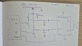
I sketched up an idea that seems workable- but always I seek the perspective of others.
Using two small signal MOSFETs, I convert the PWM to open-drain, with matched pullups. The pullup resistors are tied to a variable DC voltage- the voltage on the drains are now a variable-amplitude square waves.
An RC low-pass removes the carrier, leaving a differential analog signal, this gets AC coupled into the two inputs of the class-D amp.

I was trying to imagine if this could be done simpler with some switching diodes, need to ponder this...
The diodes are fast- I am concerned that the 20-50 nS propagation delay of the MOSFET might introduce some nasty distortion, especially near the ends of the duty cycle range?

I don't need great control linearity, and the volume does not need to go all the way to zero.
Clicks and pops when switching this on-and-off are not wanted, it needs to be low power when OFF as well.

Comments invited!
32698.jpg32698.jpg
 

Attachments

Last edited:

Ian0

Joined Aug 7, 2020
13,126
Why can't you read the control voltage with the MCU's A/D then multiply the signal that is generating the PWM by the control voltage before it is sent to the timer?

If that doesn't work, get a pair of SPDT analogue switches, connect the PWM to the control input of the analogue switch.
Buffer the control voltage with an op-amp and connect to the N/O side of the analogue switch, and connect the N/C side to ground.

Must the PAM8302 have a differential input? Can't you connect one side to ground and drive the other?
 

MisterBill2

Joined Jan 23, 2018
27,462
The data sheet for that PWM amplifier tells me quite a lot aabout it by what is not included. And the low distortion operation is at levels well below one watt, which is very adequate for listening at reasonable volume settingd with headphones. But this little IC will not deliver "room filling sound levels"at any low distortion level. I am thinking also that it will need a heat sink , which is not discussed that I could see.
Certainly it will provide thesolution for a minimum parts amplifier.

What I see is that the inputhas both inverting and non-inverting inputs, both referenced to the DC supply common side. That does not typically mean that it is a differential input requirement. It is a "ground referenced" input arrangement, with the COMMON being identified as "ground."
Mostly, in audio amplifiers thesource feeds the non-inverting (+) input while the inverting input is used for negative feedback to reduce distortion and noise.
 

Thread Starter

Sensacell

Joined Jun 19, 2012
3,784
Why can't you read the control voltage with the MCU's A/D then multiply the signal that is generating the PWM by the control voltage before it is sent to the timer?

If that doesn't work, get a pair of SPDT analogue switches, connect the PWM to the control input of the analogue switch.
Buffer the control voltage with an op-amp and connect to the N/O side of the analogue switch, and connect the N/C side to ground.

Must the PAM8302 have a differential input? Can't you connect one side to ground and drive the other?
If I understand you correctly- you are suggesting that I scale the signal at the PWM input?
The problem I see here is that the already low 8 bit resolution will be highly degraded at low sound levels, as you scale the bits down.
 

Thread Starter

Sensacell

Joined Jun 19, 2012
3,784
The data sheet for that PWM amplifier tells me quite a lot aabout it by what is not included. And the low distortion operation is at levels well below one watt, which is very adequate for listening at reasonable volume settingd with headphones. But this little IC will not deliver "room filling sound levels"at any low distortion level. I am thinking also that it will need a heat sink , which is not discussed that I could see.
Certainly it will provide thesolution for a minimum parts amplifier.

What I see is that the inputhas both inverting and non-inverting inputs, both referenced to the DC supply common side. That does not typically mean that it is a differential input requirement. It is a "ground referenced" input arrangement, with the COMMON being identified as "ground."
Mostly, in audio amplifiers thesource feeds the non-inverting (+) input while the inverting input is used for negative feedback to reduce distortion and noise.
A bit more context- this is for a small tabletop game device- the user sits with this directly- the sounds are just to add emotional impact to the gameplay, low power levels ~ 1/2 W is fine.
The PAM8302A is tiny, efficient, and $0.25 in volume. It also has a shutdown input, perfect for low-power systems.

My thinking that the differential configuration will keep the noise floor down, which adds a lot to the feeling of sound quality, the 3.3V rail is very noisy.
All the nasty junk on the supply will appear as common mode signals on the analog audio, which should be largely rejected.
(But is this "Cargo Cult Engineering?)

The idea of using the Complimentary PWM as the output directly is fairly obvious- direct class-D- but then I have no clear avenue for controlling the output volume, besides scaling the bits.
Also- I have to consider the software crash condition- that it locks-up the PWM, causing the bridge to apply full power DC to the speaker?

Any other clever solutions to deliver audio from an STM32 microcontroller?
 

Ian0

Joined Aug 7, 2020
13,126
My thinking that the differential configuration will keep the noise floor down, which adds a lot to the feeling of sound quality, the 3.3V rail is very noisy.
All the nasty junk on the supply will appear as common mode signals on the analog audio, which should be largely rejected.
(But is this "Cargo Cult Engineering?)
If you have 8-bit audio, the noise floor is already horrible (-48dB)

If I understand you correctly- you are suggesting that I scale the signal at the PWM input?
The problem I see here is that the already low 8 bit resolution will be highly degraded at low sound levels, as you scale the bits down.
Yes, but I was assuming that your audio was at least 16-bit quality.
Any other clever solutions to deliver audio from an STM32 microcontroller?
They have I2S interfaces. Plenty of Class-D amplifier ICs also have I2S interfaces.
 

Thread Starter

Sensacell

Joined Jun 19, 2012
3,784
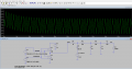
It took me a while to figure out how to generate the modulated PWM in LT Spice, but here is what I came up with.

Mind you this circuit represents HALF of the circuit, the other half is identical and drives the opposite differential input of the PAM8302A amplifier.
The other half is driven with inverted PWM.

The diode clamp controls the amplitude of the PWM signal that gets applied to the filter.
The filter drops the output voltage down to 280 mV at full volume, which is about right to drive the PAM8302A inputs, down to 24 mV when V control is = 0V

I changed my PWM system to do 10 bits at 100kHz, PWM, I used u-Law coding at 8 bits, which expands to 10 bits to drive the PWM.

It's a little herky-jerky, but I cannot find a simpler, cheaper solution.

I have the PWM working on my STM32, still waiting for some PAM8302A's to arrive in the mail to test.

I would use a I2S chip like the TFA9879 if I had enough serial engines available, I do not in my current system.

filter_Volume_Test.png
 

Attachments

Last edited:

Thread Starter

Sensacell

Joined Jun 19, 2012
3,784
The big question is about the results! What does the output sound like?
I will report back once I get the amplifier chips.

The signals observed on the scope look very clean.
I will probably need to fiddle with the timings of the enable signals to quash clicking and popping.
 
Last edited:
Top