Facebook
 Google
 GitHub
 Linkedin
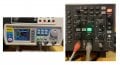
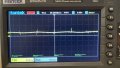
When you say triggering do you mean connecting the signal generator output to the external trigger input on the scope?I did this with real components that I have on hand, L = 22 μH, C = 10 nF.
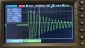
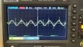
I had no problem finding a maximum amplitude at the resonance frequency of 340 kHz.
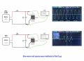
Function generator sinewave output is 1 V amplitude with 600 Ω output impedance.
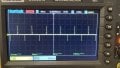
Make sure that the triggering on the oscilloscope is setup properly.
Simplest way to observe resonant frequency
- Thread starter Tutor88
- Start date