Simplest 24V 0.5A LED strip on/off toggle curcuit ?

Thread Starter

oslosl

Joined Jan 13, 2023
270
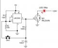
How can I make a simple 24V 0.5A LED strip on/off toggle curcuit, that can work in this setup ?
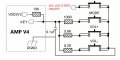
I have to make a small pcb for the resistors and capacitor anyway, so I could just add this curcuit there.
It should start off when the system is powered on.

arylic io.jpg
 

Attachments

Last edited:

AnalogKid

Joined Aug 1, 2013
12,043
Is 24 Vdc the only power source for the circuit?

The circuit is called a toggle flipflop. You can build one with discrete components, or use an IC with an outboard driver transistor. Here is an example from another thread.

NOTE: This schematic is under review.

ak

Toggle-1-c.gif
 
Last edited:

Thread Starter

oslosl

Joined Jan 13, 2023
270
Is 24 Vdc the only power source for the circuit?

The circuit is called a toggle flipflop. You can build one with discrete components, or use an IC with an outboard driver transistor. Here is an example from another thread.

ak

View attachment 344311
The amp run on 24V, but also has 3.3V or 5V output. I would prefer a small IC for less components. Which could that be ?
 

sghioto

Joined Dec 31, 2017
8,633
Is that switch for the LEDs committed to a ground connection or are both pins free?
If both pins are free this classic 555 circuit can work.
1741729273258.png
 
Last edited:

AnalogKid

Joined Aug 1, 2013
12,043
Note that for many toggle circuits, neither side of the switch is connected directly to either Vcc or GND. If this is an issue, the solution is a toggle flipflop IC with a negative-edge clock input.

ak
 

AnalogKid

Joined Aug 1, 2013
12,043
1 - IC = 8
3 - R = 6
2 - C = 4 (don't forget the 555 decoupling cap)
1 - Q = 3

I'll grant you the two unused 555 pins, so 19. If you go by the book and add a noise filter cap to pin 5, you're up to 22.

ak
 

sghioto

Joined Dec 31, 2017
8,633
Technically there are only 6 solder connections on the 555.
Take another look at your circuit. I see a P channel mosfet for Q? which is upside down.
 

crutschow

Joined Mar 14, 2008
38,316
Here's the LTspice sim of a one-IC FF toggle circuit that operates with a grounded push-button switch:
One possible negative is that it triggers when the PB is released, not pressed.

The left FF in the package is configured as a non-inverting buffer with hysteresis to provide switch-bounce suppression, and generate a fast rise-time trigger to toggle the right FF.

1741737298836.png
 
Last edited:

AnalogKid

Joined Aug 1, 2013
12,043
8 pins and 76 cents, hard to beat ***once you climb over the learning curve.*** (More like the learning mountain)

UPDATE: 6 pins and 58 cents (SMT).

ak
 
Last edited:
Top