Simplest active low voltage (< 1V, full wave rectified signal) compressor/limiter.

Thread Starter

MariánF.

Joined Apr 9, 2024
7
Experimental bass limiter 0,9 - 1,5 volts.jpg

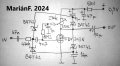
Hi all, I developed this compressor/limiter for my needs (universal low requirement audio signal processing, dead batteries use). Although a mosfet is shown, it also works with a BJT, but then it's less useful due to BJT's low input resistance. It works well with low Vgs threshold voltage and, if possible, low inner capacitance mosfets. Attached pictures are the basic schematic and an example of tested limiter for bass guitar (that's why the 470 kohm resistor doesn't matter there - for normal use, when using the FDV303N, you need to reduce the input resistor value to some 10 - 100 kohm for better frequency response and also increase the value of filter capacitors several times + possibly reduce the drain resistor for shorter attack times if needed), working from some 0,8 - 0.9 volts (the trimmer is to set the drain voltage to half of the supply, but it's not really necessary, only at low supply voltages). Depending on the diodes used, resistors can be connected in series with the output diodes to reduce the inrush current (instead of the resistor at the supply branch). The typical drain resistor values tested were 47 - 1000 ohm (it must be quite small because of reasonable attack time), the filter capacitor values were 4.7 - 100 microfarads and the input resistor values were 10 kohm to 1 Mohm.
Basic schematic.png
 

Attachments

Last edited by a moderator:

Thread Starter

MariánF.

Joined Apr 9, 2024
7
I will also add that this diode limiter works with a change in the dynamic resistance of the diodes and therefore the size of the input resistor R3 is related to the size of the filter capacitors C3 and C4. The smaller R3, the larger C3 and C4 must be, also at larger input voltages the filter capacitors must be of larger value. Usually a combination of a 470 kohm resistor and 4.7 microfarad capacitors works fine. This limiter produces clean undistorted sound without noticeable noise if the ratio of resistance and capacitance is correct. This is not a diode clipper!Basic schematic.png
 

Thread Starter

MariánF.

Joined Apr 9, 2024
7
I originally developed this limiter for telecommunications equipment, but I tested it on everything possible. How it works: if a signal is received at the input, through diodes D1 and D2, capacitors C3 and C4 begin to charge, and when a certain voltage value is reached, diodes D3 and D4 with opposite polarity begin to conduct and thus reduce the level of the input signal. This limiter operates at extremely low voltage levels, so there is no noticeable signal distortion if the ratio of input resistor R3 and filter capacitors is correct - because this affects the decay time constant, which also varies with signal strength. I usually find a minimum value of 220 milliseconds to be OK. The attack time depends on resistor R1 together with filter capacitors. Therefore, R1 should be as small as possible, with an acceptable current or attack time. But that's not a problem at those low voltages. I usually like the attack time to be less than 5 milliseconds. In practice, the resistor R2 must be divided and a filter capacitor must be connected there to increase the input resistance and amplification. The frequency range is affected by the internal capacities of the transistor and the diodes, therefore a smaller R3 is better.
 

LowQCab

Joined Nov 6, 2012
5,101
Who knows ..........
maybe, just maybe, the Input and Output-Levels will be reasonably usable and
the huge distortion might just sound like You meant it to sound like that .........
No-really, that's the way it's supposed to sound, isn't it cool ?

If this Circuit was actually practical,
the super-plentiful garbage Stomp-Boxes would have been using this design for ~65-years,
but they don't, and for excellent reasons.

An excellent Compressor / Noise-Gate can certainly be built at home,
but the huge cost in time and money makes the Pawn-Shop your most cost-effective route.
( I'm assuming that You are trying to make this project as cheaply as possible )
( It's not likely to provide satisfactory performance unless your standards are really, really low ).

Beringer has very low prices for brand-new Stomp-Boxes, as low as ~$29.oo,
and full-blown Rack-Mount, Effects-Packages for less than ~$200.oo.

If You really want to build your own top-notch Compressor at home,
I'd almost be willing to take the time to design one for You.
It will probably cost around ~$100.oo US in parts, and take You around ~40-hours of labor to get it right,
( unless you're experienced in building semi-complex Electronic-Projects, then more like ~20-hours ),
but it will do anything that You need for your Bass with the simple twist of a knob.
.
.
.
 
Last edited:

Thread Starter

MariánF.

Joined Apr 9, 2024
7
Who knows ..........
maybe, just maybe, the Input and Output-Levels will be reasonably usable and
the huge distortion might just sound like You meant it to sound like that .........
No-really, that's the way it's supposed to sound, isn't it cool ?

If this Circuit was actually practical,
the super-plentiful garbage Stomp-Boxes would have been using this design for ~65-years,
but they don't, and for excellent reasons.

An excellent Compressor / Noise-Gate can certainly be built at home,
but the huge cost in time and money makes the Pawn-Shop your most cost-effective route.
( I'm assuming that You are trying to make this project as cheaply as possible )
( It's not likely to provide satisfactory performance unless your standards are really, really low ).

Beringer has very low prices for brand-new Stomp-Boxes, as low as ~$29.oo,
and full-blown Rack-Mount, Effects-Packages for less than ~$200.oo.

If You really want to build your own top-notch Compressor at home,
I'd be willing to take the time to design one for You.
It will probably cost around ~$100.oo US in parts, and take You around ~40-hours of labor to get it right,
( unless you're experienced in building semi-complex Electronic-Projects, then more like ~20-hours ),
but it will do anything that You need with the simple twist of a knob.
.
.
.
OMG or LOL? Both. That LOW VOLTAGE limiter is MY invention. I do not need a new stomp-box or a jfet or vactrol limiter, I have several ones. BUT not a single works at sub 1 volt supply. This limiter is not a distortion pedal, it is a functional limiter. Do you understand? Or are you too lazy to make one and test it?
 

LowQCab

Joined Nov 6, 2012
5,101
I certainly don't think You are "stupid",
but I've played with very similar Circuits in the early ~'70's,
and they all have severe limitations and drawbacks,
especially when used with a Musical-Instrument, or other Audio.
You haven't re-invented the Wheel,
there are probably close to fifty examples available for free-download.

And as for ???? "beggar" ????, ( which I never made any type of inference to ....... ).
This is a project for an actual Bass-Guitar,
which I presume will be to create actual Music,
and You think that an excellent Beringer ~$29.oo Stomp-Box is too expensive ???,
so You are trying to make a "minimalist" Compressor for less than ~$10.oo ?,
Sorry for the confusion, but this post makes zero sense to me so far.

I even offered to provide You with a working Schematic, but You're "insulted",
an offer that I now withdraw.

Good-Luck.
.
.
.
 
Top