Simple but Perplexing Op Amp Circuit

Thread Starter

Electronics117

Joined Sep 9, 2017
27
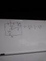
I am trying to derive the equation for finding Vout but with the only tools I have (The two golden rules of Ideal Op Amps and series and parallel circuit properties) I am stumped. Some help would be appreciated.
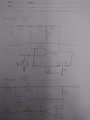
I know my attempt looks pathetic but it was the cleanest most logical attempt I have.
The line through the circuit separates the original configuration and the one I re-drew.

upload_2017-10-20_20-49-7.png

Thank you.
 

Attachments

WBahn

Joined Mar 31, 2012
32,706
Your attempt doesn't look pathetic -- it doesn't look like anything because you haven't shown any attempt at all.

What do you know about the voltage at the inverting input of the opamp (assuming that the circuit is operating in the linear regime)?

Given that, what is the current in Ra? Given that, what is the current in Rb? Keep working your way back until you get to Vout.
 

shteii01

Joined Feb 19, 2010
4,644
Here we are:

View attachment 137658

Thank you.
V3 is really Vout. You don't need V3.

Step 2.
Properties of op amps:

Property 1.
Virtual short at the op amp inputs.
This is what WBahn is alluding to. V1 is equal to Vin. For the sake of clear communication, I will keep using V1, but when we get to the end of the derivation, we will replace V1 with Vin.

Property 2.
Current does not enter op amp.
This is the second thing that WBahn is alluding to. You are going to have some current coming out of Rb. This current will enter Node V1. At this point the current should split, but it does not due to the Property 2. So. All the current that exited Rb, and entered V1, will leave V1, pass through Ra on its way to ground.
 

WBahn

Joined Mar 31, 2012
32,706
WBahn

Could the Vout really be 0 with an input on Vin though???
What makes you even ask that?

I asked you what the voltage at the inverting input of the opamp is, assuming it is operating in the linear region.

What do you know about the input voltage differential of an opamp that is operating in the linear region?
 

MrAl

Joined Jun 17, 2014
13,667
Here we are:

View attachment 137658

Thank you.
Hello,

The resistor network attenuates the Vout signal so that the voltage at the inverting input is lower than Vout.
Ask yourself, what does Vout have to be in order to make V1 equal to Vin. You might use Vin=1v for this.
Once you get that, for the test signal of Vin=1 volt, the gain is then Vout/1 which is simply equal to Vout.
 
Top