A dynamic speaker is an inductor. Its impedance is 8 ohms at a few hundred Hz but increases at higher frequencies due to the reactance of its inductance.
It might be 20 ohms at 2kHz. Then the gain of your transistor would be higher.
A dynamic speaker is an inductor. Its impedance is 8 ohms at a few hundred Hz but increases at higher frequencies due to the reactance of its inductance.
It might be 20 ohms at 2kHz. Then the gain of your transistor would be higher.
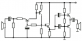
OK, I used a TIP101 and got a half way result. I used the 3rd schematic I drew. I could hear the mic if my ear was to the speaker very plainly, but never got any accoustic squeal. This transistor has a DC gain of 20000, so it has plenty of boost.
I set the collector current for 100ma, then replace the meter with the speaker.
I may try a triplett Darlington to see if that makes a difference, then give up.
LOL Bill. You had exactly the same thoughts that I did. I just bought a TIP101 today and was all excited about it, having read on wiki that the darlington pair has the product of the 2 β's.
But still you got some sort of result and thats awesome. I need to try it now.
Hello,
Sorry then i must be misreading here something.
count_volta has said that when he speaks into the mic, then it outputs an ac signal of 0.1V amplitude.
Now you say that "the diode junction will only change a little in voltage in response to the mic".
Dont these two versions contradict each other?
I guess i just dont understand a basic thing, why when you start speaking into the mic (assuming continuously), the vBE voltage doesnt turn to be: vBE = VBE + vbe = ~0.7V + 0.1Vsin(ωt) ?
When I measured the voltage of the microphone and got 0.1V-0.8V the microphone was connected directly to the multimeter and not part of any circuit. This particular multimeter is pretty expensive and can pick up millivolts. I was just trying to see how high of a voltage is produced by speaking normally vs yelling and etc.
I bet if I scream into the Darlington circuit that Bill posted recently it will work perfectly.
I ask interesting questions. Heh cool. I am just beginning to learn all this and trying to separate the theory from real life. Most people in my department (me included) think that the lectures in the EE dept could be a little more lively. That is the reason why I joined my local robotics club in my dept.
Thank you so much for the recent information especially on page 12, I need to read it as soon as I get off work.
I just read over AAC again. The amplifier you talk about in the BJT section and that I posted in the very first post of this topic has an input voltage of 1.5 volts AC.
What I was saying before in a previous post about getting 0.8 volts as output from my microphone is pure nonsense. I forgot that I had the multimeter set to millivolts!!! Below I correct myself.
I just measured my speaker (using as microphone) with a sensitive multimeter as I spoke into it. It measured 0.2 millivolts aka 2X10^-4 volts.
Since the speaker is 8 ohms the current through it is .025 mA. Now assuming that is the signal part of the current through the base and if everything was ideal multiply that by a β of 100, we get 2.5mA. Umm no wonder I can't hear anything.
Bill you said you had some crappy, but still success with a Darlington. That does make sense, if the gain of a Darlington is in the 1000's we get a much higher current at the speaker. I need to try my TIP 120 that I bought.
What do people really use to amplify the output of a microphone? These values are microscopic.
Lots and lots of gain. Generally a good amp with good speaker drive (I'm not talking audiophile quality here, just adaquate) has around 5 or 6 transistors. Since gain is multiplicative, you don't need to max out every transistor to make it work like the basic amp does.
When you adjust it, go for 100ma on the collector. I picked that figure out of the air, but it was a good number. With 8Ω speakers, it works out to 0.8V, not bad for a 3V power supply.
You must use a voltage amplifier and a current amplifier. The voltage from a microphone is much too low to drive a speaker if you simply amplified its current.
I would define 8Ω as fairly low impedance, which means it is more of a current device than a voltage device. What would you recommend to buffer a dynamic microphone AG?
I'm still trying to understand why DC stabilization would increase the gain of a Darlington. I'll be running that experiment when I have the time and energy, as I'm a bit skeptical.
I'm also going to combine the 2N2222 with the TIP101, and leave the voltage at 3VDC.
I would define 8Ω as fairly low impedance, which means it is more of a current device than a voltage device. What would you recommend to buffer a dynamic microphone AG?
I believe that he meant to connect the mic through a voltage amplifier, not a voltage buffer.
The problem which he mentioned was not that the "source resistance" of the mic's not low enough (which in such case, you'd want to use a voltage buffer), but that the output voltage of the mic's too low.
I believe that AG's idea was:
Mic ---> Voltage amplifier ---> Current amplifier ---> Speaker.
What is wrong with using the BJT as a current amplifier? By the law of electromagnetic induction when I speak into a microphone a voltage is induced which produces a current in the coil.
What is wrong with amplifying that current? It is ultimately due to this current that the diaphragm of the speaker moves and you hear the sound. Isn't the common emitter amp basically a current amp? Beta is the common emitter current gain.
Ultimately, nothing is wrong with it. There is usually an optimum design that works best, which is what I think people are talking about. I tend to follow my signature though.
What is wrong with using the BJT as a current amplifier? By the law of electromagnetic induction when I speak into a microphone a voltage is induced which produces a current in the coil.
What is wrong with amplifying that current? It is ultimately due to this current that the diaphragm of the speaker moves and you hear the sound. Isn't the common emitter amp basically a current amp? Beta is the common emitter current gain.
Assume that the speaker looks like an 8Ω resistor. In order to get a current I to pass through the resistor, you must apply 8*I volts. If you take the output of a speaker used as a microphone and apply it to an emitter follower, the follower will indeed be capable of supplying a larger current, but it will only actually do so if there is also enough voltage to make that current pass into the load. You need voltage gain as well as current gain to make this project work.
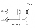
I wired up the circuit shown in the image borrowed from Bill, with the addition of a 470μF electrolytic from the wiper of the 10k pot to the emitter.
I used a couple of identical 8Ω, 2" computer speakers rated for .2W. I figured they could tolerate 100 mA of DC without damage.
I used a TIP31 bipolar transistor and adjusted the 10k pot until I had about 50 mA of collector current. The supply voltage was 2 volts.
I moved the speakers close together and at about 1.5" separation, I got acoustic feedback.
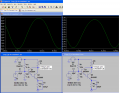
I've attached a scope capture showing the voltage at the base and at the collector. As can be seen, the voltage gain is about 13. And, of course, there's current gain as well, which I didn't measure.
With a collector current of about .05A, we would expect the voltage gain to be (8*50)/26 ~ 15, a fairly respectable agreement with the measured gain.
If you take the output of a speaker used as a microphone and apply it to an emitter follower, the follower will indeed be capable of supplying a larger current, but it will only actually do so if there is also enough voltage to make that current pass into the load.
In other words you are saying that the current must overcome the 8Ω of the speaker at the output in the collector side, and for that you need a large enough voltage drop on the 8ohm speaker? Doesn't this voltage come from the battery connected to the collector. In Bill's circuit it was 3 volts. In my real life circuit it was 4.5 volts. Isn't that enough? The resistor/speaker takes as much voltage as it needs to pass the collector current through it.
In other words you are saying that the current must overcome the 8Ω of the speaker at the output in the collector side, and for that you need a large enough voltage drop on the 8ohm speaker? Doesn't this voltage come from the battery connected to the collector. In Bill's circuit it was 3 volts. In my real life circuit it was 4.5 volts. Isn't that enough? The resistor/speaker takes as much voltage as it needs to pass the collector current through it.
The extra voltage comes from the battery if the circuit is a common emitter amplifier.
If it's an emitter follower, you can't get more voltage out than you put in, even if the battery is at a higher voltage; in fact, you get a little less out than you put in.
The circuit I wired up and described still works (oscillates with acoustic feedback) with a supply voltage of 1 volt, but just barely.
Not if the transistor is wired as an emitter follower. In that case, the transistor's emitter will supply the larger current only if the impedance of the load is low enough to sink that larger current when driven by the same voltage as is present at the base of the transistor.
It would probably be more accurate to say (for an emitter follower), "The resistor/speaker takes as much current as the voltage at the emitter can force through it.", and the voltage at the emitter can't be greater than the voltage at the base.
This means that using a speaker as a microphone to drive an emitter follower, which then drives another speaker, is going to give approximately the same result as using a speaker/microphone to directly drive another speaker, without any transistor gain stage at all.
The voltage applied to the second speaker in the case of the direct connection will be 1/2 of what it will be if an emitter follower is interposed between the two speakers, due to the voltage divider effect. With the emitter follower in place, the speaker/microphone sees a much higher load impedance (approximately the speaker impedance multiplied by β), than it does when driving the second speaker directly, so it isn't loaded enough to cause the voltage from the speaker/microphone to drop by 1/2.
But, even with the emitter follower in there, the second speaker doesn't see any higher voltage than what the speaker/microphone puts out, and that's not enough to cause acoustic feedback. But, it is enough to hear from the second speaker, if you connect the two with a cable long enough to separate the two in different rooms, and get someone to talk into the first one while you put the second up to your ear. This is the sound-powered intercom technique.
If you want more current in the speaker such as the current gain of an emitter follower can provide, then you will have to increase the voltage with some other means than an emitter follower.
You can see from my description of the single transistor stage I wired up that you can get enough gain to cause acoustic feedback with only that one transistor, but if you want really high-powered output, one stage won't do it.
The standard way to get high power is (roughly speaking) to first get the voltage gain with common emitter stages, followed with an emitter follower to get the final current gain.
Wait, who is talking about an emitter follower? I am trying to do this with a common emitter amp. That is why I was like, what is he talking about. LOL.
Did I miss a discussion started on another page about a common collector amp? I am just beginning to learn about this and don't want to stray away from the common emitter amp for a while at least.
I always take my output at the collector and ground the emitter. Or that is what I have been doing for this experiment anyway.
Thank you for the information though. I have yet to read the common collector section of AAC. It all helps. I am still beginning to learn. It might seem slow for you pros.
The extra voltage comes from the battery if the circuit is a common emitter amplifier.
If it's an emitter follower, you can't get more voltage out than you put in, even if the battery is at a higher voltage; in fact, you get a little less out than you put in.
The circuit I wired up and described still works (oscillates with acoustic feedback) with a supply voltage of 1 volt, but just barely.
Not if the transistor is wired as an emitter follower. In that case, the transistor's emitter will supply the larger current only if the impedance of the load is low enough to sink that larger current when driven by the same voltage as is present at the base of the transistor.
It would probably be more accurate to say (for an emitter follower), "The resistor/speaker takes as much current as the voltage at the emitter can force through it.", and the voltage at the emitter can't be greater than the voltage at the base.
This means that using a speaker as a microphone to drive an emitter follower, which then drives another speaker, is going to give approximately the same result as using a speaker/microphone to directly drive another speaker, without any transistor gain stage at all.
The voltage applied to the second speaker in the case of the direct connection will be 1/2 of what it will be if an emitter follower is interposed between the two speakers, due to the voltage divider effect. With the emitter follower in place, the speaker/microphone sees a much higher load impedance (approximately the speaker impedance multiplied by β), than it does when driving the second speaker directly, so it isn't loaded enough to cause the voltage from the speaker/microphone to drop by 1/2.
But, even with the emitter follower in there, the second speaker doesn't see any higher voltage than what the speaker/microphone puts out, and that's not enough to cause acoustic feedback. But, it is enough to hear from the second speaker, if you connect the two with a cable long enough to separate the two in different rooms, and get someone to talk into the first one while you put the second up to your ear. This is the sound-powered intercom technique.
If you want more current in the speaker such as the current gain of an emitter follower can provide, then you will have to increase the voltage with some other means than an emitter follower.
You can see from my description of the single transistor stage I wired up that you can get enough gain to cause acoustic feedback with only that one transistor, but if you want really high-powered output, one stage won't do it.
The standard way to get high power is (roughly speaking) to first get the voltage gain with common emitter stages, followed with an emitter follower to get the final current gain.
wow, I learned a lot from this post
I just finished learning today the theory behind the emitter follower amplifier and it was great to receive some practical point of view on this.
Everything you said appears in my notebook, it was so amazing.
Dont you think that the 8ohm speaker's impedance that is connected at the emitter follower's output is too low, which will significantly degrade the voltage amplification?
Rout of an emitter follower is certainly much larger than this 8ohm speaker's impedance, so the voltage which the second amplifier will eventually receive will be approximately Vin * R_speaker / Rout.
And in post #132, when you said "What is wrong with using the BJT as a current amplifier?", you seemed to be asking about current amplification alone.
If you will wire up the circuit I showed, you should get enough gain with a 2N2222 to get acoustic feedback. Lower your supply to 2 volts if you can, and run with a current of .05A and the 2N2222 shouldn't overheat. If it gets too hot, heatsink it.
 Facebook
 Google
 GitHub
 Linkedin
")