Hey, i've been reading this thread and I must say that i learned a lot from you guys.
I'd like to say a special thanks to millwood, i learned a lot from your detailed posts here.
Thanks guys
I apologize for jumping in here audioguru,
Thankyou.
MILWOOD,
Hi,
I'm sorry if I gave the impression, that I'm some kind of electronics engineer,
I am NOT and further more I NEVER professed to be a electronics engineer.
I am a HOBBYIST, when it comes to electronic circuit design, electronics is just a hobby to me
of many of my hobbies, I like to design transistor circuits, with the best of knowledge I have,
and I have succeeded with a lot of my projects, in doing so.
If the OP, would have asked for a hi fidelity amp, I would have kept OUT of this, but he wanted
something to JUST come out of the speaker, to give him some encouragement, in designing an amp,
so when I posted my circuits, I did them quickly on the fly, using what was available, and easy to come by, such as 2 8 ohm speakers.
That's why I stressed in my post that this is not the proper way to drive such a low load, but wanted to show him, that even when these situations are worst case you can learn a lot about
design work by working around the mismatches impedances, and still be able to come up with a
reliable circuit.
That's what I did, and both my circuits worked beautiful, on the 3 stage circuit, I could hear clearly a whisper from a short distance on the output speaker, I was getting a lot of acoustical feedback, then the second circuit, worked just as well but not as sensitive as the first but very clear audio output, when I hold the output speaker close to my ear,
I am well pleased that I can take these worst case scenarios, and learn how to design around it to give me a decent result. (I must stop here and GIVE credit where credit is DUE,I thank my LORD and SAVIOUR JESUS CHRIST, for giving me the ability to be able to have some understanding in electronic circuit design)
I am NOT designing comercial grade circuits, I am a gadget builder, in circuit design...
Here are some of the things I do know to some extent about audio amp design.
That just throwing a capacitor of any value across a resistor at the emitter, is not
professionaly done, why because ,that the reactance of the cap, needs to be within the range, of frequency response as well as not decreasing input impedance,
That there needs to be calculations done to get the proper value of cap needed,
that cap coupling between stages, need to be properly chosen, due to phase shift, caused by RC sections of each stage. I also understand to some degree, Sometimes you need to design the coupling of each stage with a different roll off in frequency response, so as to keep the phase shift minimal, Also sometimes you have to use a split emitter resistor, and partial bypass cap.
that you need to take into consideration all the parrallel impedances going into a stage, then design the driver stage with a lower Rout.
that by putting a capacitor between base and collector, only limits to a greater degree the high frequency response just as the internal cap. in the transistor, denotes the high frequency cutoff. Its better to put a resistor in there as well.
that neg. feedback is good for an amp. while pos. feedback is not. (unless its an oscilator)
that there needs to be some sort of filtering to decouple the supply from the signal currents.
that MAX. values need to be taken into consideration, and that sometimes you need to implement other transistor config. to aquire a given output.
that you can't just hook up a transformer to a transistor stage with out taking into consideration reflective impedances, that also must be put into the Av. calculations.
that the input signal needs a high input impedance to work into so as to keep the integrity of that signal strength.
that max power transfer is not nessarily when impedances are equal.
That sometimes at much higher frequencies being amplified there sometimes needs to be peeking coils inserted, shunt peeking or series peeking.
Also the filtering that needs to be designed into a stage, when amplifiing a given bandwidth.
And yes, 3 DB. down 0.707 and all that stuff that deals with the bandwidth.
L sections, T, and PI, formations, and M-derived stages of filtering, for amplifiing a given band.
NOW
I apologize for loosely using the phrase " that designing an amp is easy with just a few ohms laws and calculator and your on your way"
I was WRONG to use it that way, it would be an insult to someone who has a life long career in this field, to hear it put that way,,,I DID NOT SAY IT MEANING IT TO INSULT THOSE IN THIS FIELD, in fact I didn't think anything about it until you wrote what you did.
Then I seen where it could be a little insulting to those in this field.
My own family menbers look at all this stuff that I design and build, and say with amazement, why don't you become an electonic engineer, and I always say, this stuff that I know is just basic, compared to what electronic engineering is all about. I have my course books to show me that, No, GOD gave this to me as a hobby, to enjoy, learning to design circuits from scratch.
That's the fun of it for me....
Thankyou and GOD BLESS..
this is to illustrate that designing an amp is a lot more than just getting its dc working points right.
Again, I strongly suggest that you pick up a book by Self or Sloan on the subject matter and after that, you will have a lot more appreciation for the issues engineers have to deal with to produce even a half respectable product.
it also shows why so many textbook examples will never be used in the real world, .
Your absolutely right about that quote above, I'm trying the best I can to try to stick to the proper way of designing an amp, I've started a blog category, to record my design sequence, and had to start over at least 3 times already, it so tempting to just throw capacitors in there experimentaly to get the results I use to get by trial and error, but I am realizing there is a lot of impedance matching, and base voltage calculations that need to be made so as to not have the stages overdriving one another.
This is a real learning challenge, I will look over all the things you posted on this thread and gleam as much information I can that you presented, in here because thewre is a wealth of design information you give on this forum, and I for one would like to say thankyou, for the time and work you put forth to help us in these design situations.
Thanks again...
I've noted in your schematics that you recommend for neg. feedback to use the collector shunt voltage feedback cinfig. That's something that I mostly skipped over in my course books, thinking that it was not as good as series current feedback but I'm going to read up on it and take notes and learn how to use this feedback the best I can.
the difficulties in designing a discrete circuit or choosing one for a project is to understand your priorities. like anything in life, circuit designs are decisioned made with many compromises. and to make a good circuit, you have to know what you are willing to sacrifice in order to get the things you want the most.
that's the same with emitter vs. collector feedback. Emitter feedback is fast, provides better linearity, and helps with DC stability.
But it causes the transistors to run lean (at lower idle current, everything else being equal), and forces the use of high collector resistors which leads to high output impedance. so it would be the wrong thing to use if you are using it to drive a speaker or headphone.
On the other hand, if you are just using it as a preamp where the load is typically of high impedance, you want to use more emitter feedback.
vice and versa. the right choice depends on your particular design circumstance.
1) topology: you need to decide pretty early on what kind of amplifier this is going to be. is it going to be multi-stage, or single stage, dc coupled or ac coupled, dual rail or single rail, current feedback vs. voltage feedback, SE / push pull? buffered or not? etc.
2) DC working points: how hot / cool do you want to run the amp; how resistant should it be to rail ripples, etc.
3) ac performance: gain? stability? frequency response? input / output impedance?
4) noise? transient performance? power-on / power-off characteristics? power consumption? device requirements? etc.
th process is usually iterative and the first three stages can typically be done with a computer and the last one usually requires physical prototyping.
take this design for example. Let's say that we want to design a single-rail audio preamp. the gain typically is 5x and it takes line-level signal, and drives a load > 4.7k. Input impedance is preferably greater than 10k.
so a single stage a/c coupled should work. audio amps usually run around 1ma. to maximize the output swing, we want Vc to idle at 1/2 rail + Vce(sat). since we can output 5v Vp (5x gain), we need a Vpp of 10v, so 16v rail is needed and preferably 24v to have some headroom.
at 24v rail, and Vc=12v+1v for saturation, and idle at 1ma, that means the collector resistance should be (24v-12v-1v)/1ma=11k. without any feedback, and no buffer, that means my output impedance would be 11k, far greater than my required output impedance of 4.7k. so I can either increase the idle current (to reduce Rc), add a buffer (complexity), or sacrifice the output impedance requirement of 4.7k. I typically would just add a buffer. But for demonstration purposes, we can lower Rc 4.7k or 2.2k to match the output impedance and to increase idle current to 11v/4.7k=2.5ma.
for a gain of 5x, that means my Re is now Rc/gain=4.7k/5x=1k.
my base potential is then 0.7v+Re*idle current = 0.7v+1k*2.5ma=3.2v, or 15% of rail voltage.
given that the input impedance needs to be at 10k, and it is typically dominated by the lower resistor (in our topology), so the lower resistance R1=10k, and the upper resistance R2=10k/15%*(1-15%)=57k.
here is the amp. it idles at about 2.7ma vs. 2.5ma expected, with a base potential of 3.4v, vs. 3.2v expected.
the gain is 4.5x with a very light load. if you tie a 4.7k load to it, the gain will be 2.3x. not good.
it also has poor ripple rejection and isn't very DC stable.
so the first thing to do is to introduce some negative feedback. The simplest way to do it is to wire the upper resistor to the transistor's collector.
since Vc is at 1/2 rail (roughly), that means my Vb would be halved as well. so to maintain the idle current of 2.5ma, I need to half the Re resistor from 1k to 470ohm.
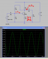
here is the new amplifier powering a 4.7k load.
it idles at 2.2ma, with a Vb of 1.7v, and Vc of 12.6v. the output is 9v Vpp while driving a 4.7k load (a gain of 4.5x with the load). clearly it is an improvement over the previous design.
so the first thing to do is to introduce some negative feedback. The simplest way to do it is to wire the upper resistor to the transistor's collector.
since Vc is at 1/2 rail (roughly), that means my Vb would be halved as well. so to maintain the idle current of 2.5ma, I need to half the Re resistor from 1k to 470ohm.
here is the new amplifier powering a 4.7k load.
it idles at 2.2ma, with a Vb of 1.7v, and Vc of 12.6v. the output is 9v Vpp while driving a 4.7k load (a gain of 4.5x with the load). clearly it is an improvement over the previous design.
In the simulation shown, there is no negative feedback. Since you have a driving source with zero ohms output impedance, any negative feedback is shorted to ground through the source.
If you go back to the previous circuit and make the emitter resistor 470 ohms and adjust R1 to get the same 12.6V quiescent collector voltage, then it will also drive a 4700Ω load to ~9V P-P. Actually, it will drive the load to slightly more because it won't have the additional ~57k load due to R1.
So, when driven by a very low impedance source, the AC performance of the second circuit would not be much of an improvement over the previous design, if any.
Actually the OP has two different schematics, one is similar to this, which is what millwood keeps discussing.
I went from this schematic, which was similar to the other schematic shown, and millwood and I spent the next 3 pages discussing apples and oranges. Frustrating. It didn't do me any good to clearly show what I was talking about, so I have to conclude there is an element of arguing for arguments sake.
so it is other people's fault that you failed to discuss the circuit that the original poster was asking for help on, in his very first post?
and it is other people's fault that you failed to recognize repeated reminders by others that they were talking about the circuit the original poster wanted to talk about and the one that you refused over and over again to talk about?
Yes, if you insist on ignoring other peoples posts. Makes you look less than professional. Notice you're doing it to Wookie too, one of the other regulars here.
The OP showed both schematics, I showed schematics to point which one I was referring to, and proceeded to discuss it. I don't know what you're doing, but I know you now.
Back to the regularly programmed discussion. This is the OPs thread, not yours.
you mean your failure of understanding a discussion before jumping in? or your failure of recognizing repeated efforts to tell you that they are NOT discussing what you are discussing?
I have noticed there are several threads on-going at the moment that are straying off-topic where either the original topic is not being discussed, it is not being discussed constructively, or there is point-scoring and ad-hominem attacks.
Keep the discussion on-topic and civil. You can debate and have disagreements without resorting to being discourteous or having an attitude. Ad-hominem attacks are always off-topic.
This applies to everyone.
Any further posts in this theme will be deleted, and where necessary privileges removed. Discuss the topic at hand. If you want to address this with me, please do so over PM not here in this thread. Thank you.
Guys thank you for the information, and I will read it all later, but can you please answer a specific question without showing me 100 circuit variations and throwing equations at me?
Its supposed to be sensitive. Is this better than a dynamic microphone for Bill's circuit? This circuit below. Replace the carbon mic with it lets say.
I have an idea of how the mic works, but not really sure how to connect it since it requires a voltage to operate. I suppose the voltage from the collector node will do that right?
Bill could you perhaps modify the above schematic for a condenser mic?
Thank you.
P.S. I tried the above schematic by using 8 ohm speakers for both the speaker and mic, and nothing, silence. A speaker diaphragm is not designed for responding to vibrations in the air, while a microphone diaphragm is.
If it is a dynamic speaker (remember what I said about the physics and how many types there are.) it will work better than most mikes, but the frequency response won't be as good.
A condenser microphone is much harder to use. We are trying for simplicity (I thought). A carbon is much easier to use (which is why it was the standard for the phone company from before tubes were invented until LSI, large scale integration). A carbon mic really doesn't need much of an amp, while a condensor mic generates much smaller signals.
So did you get any readings with a DVM off this circuit? If you want I'll throw something together and test it along side, but electrit and condenser mics are close cousins, don't use them until you have something better to drive a speaker with.
The quickest way to tell if it is working is to put the mic next to the speaker. If you have acoustic squeal then it's happening.
You do not have a condenser mic. You have a cheap electret mic that was sold at a very high price. It is 21 years old (made in 1988).
It is not sensitive, needs to be powered and needs to be amplified with a preamp circuit.
You do not have a condenser mic. You have a cheap electret mic that was sold at a very high price. It is 21 years old (made in 1988).
It is not sensitive, needs to be powered and needs to be amplified with a preamp circuit.
It so happens that I did not buy it. I took it out of a little toy I had. I actually have 2 of them which I got from a toy which costs half the price of one mic. I don't fall for such idiotic prices.
 Facebook
 Google
 GitHub
 Linkedin
")