Noob Question - Simple volume control for PC and PAM8610 amp

Thread Starter

Algray

Joined Oct 12, 2020
10
Hello everyone!

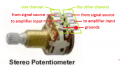
First of all, if you're beginning to read this, please understand that I am very new to electronics, I have little studies but I can at least not produce cold solder...most of the time. I also can't use the standard drawing softwares yet, as my knowledge is far from this (The attached image is a simple drawing).

Now, knowing the level of question this might be, I am planning to make a small volume control with an small board amp, that is the PAM8610.

I already have that board, and have been testing lately using a 9V .6A DC Power Supply. It already is able to achieve most of what I need, that is a low noise (idle) amplifier for small speakers. I want a simple system that I could attach a pair of speakers (or maybe bookshelf sound boxes in the future) and use as low do mid volume listening.

The simple volume control I was able to plan is...well, very simple, as far as my searches got me this far.

Right now I have a few questions regarding this small project, since I don't know what exactly I could use to minimize white noise to the output signals.

I want to keep at least one of the 2 P2 Stereo output signals being controlled by the Pot. (Which I am also not sure if I should use a 1k or 50k one)

The audio input will come from my PC (ALC1220 codec), the front P2 output will be mostly used for headphones (16 to 100 Ohm).

The back one would be to control volume when using any external amplifier or active system (I own a Edifier P3060 2.1 system, but it's volume controls are in the back of the sub...)


With this information, I am not sure which components I should use (and if it's actually needed) in this case.

I have seen that I could add a pair of 1k Resistors bridging the positive inputs to ground, adding resistance to decrease noise input, is this right? If so, is there any other resistor values I could use instead? (lower or higher than 1k?).

There's also the very common capacitor to filter the DC input. I was able to find a fairly cheap 12v 5A power supply, which should be more than this board will ever need. The extra amperage capacity this PSU can supply may harm the board? Would a 50V 2.200uf Cap be enough? (I currently have a 10V 1500uf on this 9V PSU, this would be too low voltage?)

And last question, for the ouputs (headphones and the extra), should I use a 6 pin switch to completely cut the signal on them?

Thank you for your precious time and insight!
 

Attachments

KeithWalker

Joined Jul 10, 2017
3,050
I already have that board, and have been testing lately using a 9V .6A DC Power Supply. It already is able to achieve most of what I need, that is a low noise (idle) amplifier for small speakers. I want a simple system that I could attach a pair of speakers (or maybe bookshelf sound boxes in the future) and use as low do mid volume listening.
See the attached drawing for the correct wiring.

I want to keep at least one of the 2 P2 Stereo output signals being controlled by the Pot. (Which I am also not sure if I should use a 1k or 50k one)
Both of the stero outputs will be controlled by the volume control unless you add a switch to short out one input. You can use any value of srereo volume control, preferably between 10K and 50K but make sure it has an audio (log) taper for the best volume control.

With this information, I am not sure which components I should use (and if it's actually needed) in this case.
I have seen that I could add a pair of 1k Resistors bridging the positive inputs to ground, adding resistance to decrease noise input, is this right? If so, is there any other resistor values I could use instead? (lower or higher than 1k?).
Connecting resistors across the inputs will create a mismatch for incoming signals and will not improve the signal to noise ratio.

There's also the very common capacitor to filter the DC input. I was able to find a fairly cheap 12v 5A power supply, which should be more than this board will ever need. The extra amperage capacity this PSU can supply may harm the board? Would a 50V 2.200uf Cap be enough? (I currently have a 10V 1500uf on this 9V PSU, this would be too low voltage?)
I know nothing about supply so I can offer very little advice on it. The 50V 2.2uF capacitor will filter out high frequency noise from the supply but I have no idea how effective it will be. The 1500uf capacitor has too low a working voltage.
NOTE: in your drawing, you show the capacitor in series with the power input. That will not work. It needs to be connected across the supply as shown in my diagram.

And last question, for the ouputs (headphones and the extra), should I use a 6 pin switch to completely cut the signal on them?
I don't understand what you mean by "6 pin switch".

Regards,
Keith
Amp2.jpg[
 

Thread Starter

Algray

Joined Oct 12, 2020
10
@KeithWalker Thank you for taking your time and replying!

Sorry for the hiccups on the drawing I made... I had tried creating a different drawing earlier with the correct connections across the input, then made this one after messing up hahah

I'm glad I got a 50k POT as well as the 1K. I think I saw on a video on YT that 1K would be enough for simple line input control, then saw on some other pages around google people mentioning 50K, so I got one of each just in case.

Thank you a lot for the drawing you made clarifying how to wire the potentiometer correctly!

So, to put more information and context, I also got some of these cables:

1602610868996.png

In which I plan to use for the Inputs/P2 outputs. Should I rely on making the external wiring to Ground/Common as "shielding"?

This is the "6 pin switch" I mentioned, sorry if that's not the correct name for this device, English isn't my primary language.

1602611017506.png

I think this switch would be able to completely cut signal from all wiring connected (R, G/C and L) as standard for the P2 Stereo outputs.

Once again, thank you very much for your reply and input on this!
 

Thread Starter

Algray

Joined Oct 12, 2020
10
I just noticed I done bad on this little button switch. I thought since it was a 2 position switch, it would just bridge one side to another when ON, but it's far more complex. Seems like it has 2 always on, 2 always off and 2 common pins...
 

KeithWalker

Joined Jul 10, 2017
3,050
You can use the cable you have for the inputs. The red is for the right channel and the yellow for the left. The shielding is the common ground connection for both channels.
You can use the switch you have unless it only stays closed while you are pressing it. If you connect between the common and normally open contacts on each side for each channel, the contacts will close when you operate the switch.
 

Audioguru again

Joined Oct 21, 2019
6,647
The PAM8610 cannot be connected to normal headphones that have the common of each channel connected to ground since
its outputs are bridged (each speaker has both of its wires powered with signal). Then your switch must have 8 pins and your headphones must have 4 wires. Why use an output switch, to switch between headphones and speakers?

The datasheet for the PAM8610 shows that it uses a DC volume control to adjust the volume of both stereo channels at the same time but the module you bought does not use it. Then you must use a stereo volume control (it has 2 sections, one section for each stereo channel). But I think you wrongly have a volume control for a single channel.

Maybe the instructions for your module says what resistance the volume control sections should be. The datasheet for the PAM8610 does not say since it is designed for a DC volume control.

I show how a stereo volume control should be wired. I guess it should be 10k ohms for each of its two sections.

You talked about noise but you did not explain if it is high frequency hiss or squealing or if it is low frequency hum.
You show a shielded cable with 2 wires in it but only one of the wires and the shield wire are used. The output wires to the speakers do not use the shield.
 

Attachments

Thread Starter

Algray

Joined Oct 12, 2020
10
@KeithWalker Thanks! I will wait for the components to arrive to put everything together, it should arrive in the next days this week, hopefully my delivery service doesn't mess this one up.

@Audioguru again Thank you for your input as well!

I do not plan to throw the amplified sound to my headphones. I only plan to use the potentiometer as an external volume control.

So, the signal would come from input, reach the potentiometer and then get split to 3 sides, the PAM8610 board, and 2 extra P2 Stereo outputs, no direct gain involved as I don't really use headphones with big resistances, mostly IEMs and In-Ear stuff.

And yes! That shielded cable I bought specifically for the inputs and the Stereo P2 Outputs. I have gotten parallel black/red cables for both the audio outputs from the AMP and the DC Input.

1602628005472.png Cable I will use for DC Input and Audio AMP out (vendor claims it's a 2x1,00mm cable)

I think I got the correct potentiometers. All those images are from the vendor site where I got the components.
1602627911125.png1 k Logarithmic Pot

1602627943673.png50k Log Pot

Got one of each since I saw 2 different places claiming those values before. Would you say that's either too high or too low for this type of input?

Thank you!
 

Thread Starter

Algray

Joined Oct 12, 2020
10
Your signal source will probably be overloaded if it drives 1k pots. Does it have a headphones outputs to drive the 1k volume controls?
The signal source will be my computer. I have an Asrock X370 Taichi motherboard, which uses the chipset ALC1220 codec.

It does have an "Headphone amplifier" on the frontal P2 output, but I will be using the standard back stereo output.
 

Thread Starter

Algray

Joined Oct 12, 2020
10
You need to find out if the computer can drive 1k volume controls.
I'm not actually sure how to do that, my apologies.

I have attempted finding some information on the chip itself but I had little results.

By using the 1k Pot, could I damage my computer's sound output? Or will it simply not work well as in most of the pot scale will be mute before sound signal comes through?
 

KeithWalker

Joined Jul 10, 2017
3,050
By using the 1k Pot, could I damage my computer's sound output? Or will it simply not work well as in most of the pot scale will be mute before sound signal comes through?
You will not damage the computer's output but it will probably be overloaded and distorted. Use the 50K pot.
 

Audioguru again

Joined Oct 21, 2019
6,647
The PAM8610 datasheet shows 1uF input capacitors so its input impedance must be 8k or 16k ohms for 20Hz to be at -3dB.
Then a 50k linear pot will be overloaded.
 

KeithWalker

Joined Jul 10, 2017
3,050
The PAM8610 datasheet shows 1uF input capacitors so its input impedance must be 8k or 16k ohms for 20Hz to be at -3dB.
Then a 50k linear pot will be overloaded.
From page 7 of the the datasheet, with the internal digital volume control set to maximum, the input resistance is 22.32 Kohms.
SO USE THE 50K POT !
It will not overload anything. The logarithmic tracking will just be a little less logarithmic at maximum volume, which you will not even notice.
Regards,
Keith
 

Audioguru again

Joined Oct 21, 2019
6,647
The PAM8610 Diodes Inc datasheet from June, 2013 does not say its input resistance.
Whose datasheet do you have?
With the 22k input resistance then I agree that a 50k volume control will be fine.
 

Audioguru again

Joined Oct 21, 2019
6,647
I have the Diodes Inc. newer datasheet. I did not know that PAM was Power Analog Microelectronics company who invented the PAM line of amplifier ICs then the PAM company was purchased by Diodes Inc.
When Diodes Inc. printed their newer datasheet they did not include the table with the input resistance.
Thanks, Keith.
 

Thread Starter

Algray

Joined Oct 12, 2020
10
Hello everyone! Thank you so much for all your input.

I have received my components and did the project.

Quite sadly, the 2 50k Pots I got had some bad luck. One was only working one side and the other broke one of it's legs while I was testing...

I will order new ones, for now, I completed the circuit and have been doing some tests.

Even the 1k pot cut the white noise that came from my PC, coil whine from the GPU and such... But yes, I noticed the clear loss in volume, it's not making much difference in my project as I won't be blasting the little amp at full. Even 15 RMS is loud enough where I live, pretty much an apartment.

While I was testing the 50k that worked, it would be at a fairly low volume until completely maxed out.

Here's a shameful picture of the project...IMG_20201016_154734.jpg

The board isn't held by anything but the wires right now. I tried to use the parallel cables I got but they were too thick as you can see on the DC in. While trying I screwed up one of the solder pads for the speakers hahahah...oh boy.

Anyways, I had the result I sought to, which was a small amp for playing at low~medium listening volume and a manual control for headphone volumes.

Almost forgot to mention. I will be getting more 50k pots and will change the that 1k currently in the project.
 
Top