Simple 100Mhz colpitts

Thread Starter

Zeeus

Joined Apr 17, 2019
616
Can someone please enlighten Z?

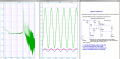
Trying to understand colpitts : still learning more but using little learned :

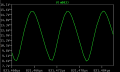
Expected about 8v pk using simple analysis and about 100Mhz but on spice the output is distorted :

Please comment about anything

Thanks

will change the bias and want to build the circuit but dunno how to get the 1uh (meter doesnt get to Uh)..air core yeah?
 

Attachments

Last edited:

MisterBill2

Joined Jan 23, 2018
18,176
What you will almost ALWAYS find is that an oscillator output will be distorted unless there is some form of amplitude control. This is intrinsic, because without something to reduce the feedback an oscillator will continue to increase amplitude until it is limited either by saturation or by cutoff limiting. A larger emitter resistor or less feedback, or a combination of both may get you to a stable amplitude with much less distortion.
In this circuit that resistor across the coil does reduce the resonant circuit's "Q" and also increases the distortion.
 

Thread Starter

Zeeus

Joined Apr 17, 2019
616
What you will almost ALWAYS find is that an oscillator output will be distorted unless there is some form of amplitude control. This is intrinsic, because without something to reduce the feedback an oscillator will continue to increase amplitude until it is limited either by saturation or by cutoff limiting. A larger emitter resistor or less feedback, or a combination of both may get you to a stable amplitude with much less distortion.
In this circuit that resistor across the coil does reduce the resonant circuit's "Q" and also increases the distortion.
Hi...but the output is not close to saturation but think i get you : next section in book on amplitude stabilization but again, output not in saturation....
 

MisterBill2

Joined Jan 23, 2018
18,176
Hi...but the output is not close to saturation but think i get you : next section in book on amplitude stabilization but again, output not in saturation....
OK about the output not being in transistor saturation, it might be going into cutoff, at the opposite extreme. One or the other will be what limits the amplitude of the oscillation. Without some form of amplitude control there will always be a limiting cycle eventually. An emitter resistor is usually the simplest way, not always the best way.
 

Thread Starter

Zeeus

Joined Apr 17, 2019
616
2nd circuit, modified:

View attachment 191084
EDIT:
Why do not use this circuit:
View attachment 191088
what is wrong with my circuit? struggling to get 1uh then 50nH??

sorry for delay in response....can you explain circuit? Also can't use your green curve circuit as requires supply not available

Please throw some light on circuit

Also, remember a long time ago you added resistor from supply to inductor point and bypassed with capacitor? (in book advised) but why not in your circuit?
 

Thread Starter

Zeeus

Joined Apr 17, 2019
616
2nd circuit, modified:

View attachment 191084
EDIT:
Why do not use this circuit:
View attachment 191088
Made the red waveform circuit but used 2pf and 30pf : atleast to see oscillation but nothing : Not sure about inductor value but atleast should oscillate but no, not working

and noticed that if C4 is changed to a higher value like 1Uf then no oscillation? why? because at 100Mhz 1uf not really a short?

need learn more but atleast to see oscillation for now but.....
 

Danko

Joined Nov 22, 2017
1,829
what is wrong with my circuit? struggling to get 1uh then 50nH??
Your load (R2) is 2k. Reactance of L1 is 628Ω.
But for frequency stability and for reliable excitation
reactance of L1 should be lower as much as possible than R2.
Selected 50 nH has reactance 31.4Ω.
So 2000 / 31.4 ≈ 64.
Also can't use your green curve circuit as requires supply not available
Pay attention to value of V1 in circuit right to green curve.
It is 12V.
Also, remember a long time ago you added resistor from supply to inductor point and bypassed with capacitor? (in book advised) but why not in your circuit?
These resistor and capacitor are important in real circuit, but not necessary for simulation.
Made the red waveform circuit but used 2pf and 30pf : atleast to see oscillation but nothing : Not sure about inductor value but atleast should oscillate but no, not working
With changed values of capacitors C3, C4 feedback power goes to emitter is not enough for oscillation.
and noticed that if C4 is changed to a higher value like 1Uf then no oscillation? why? because at 100Mhz 1uf not really a short?
Circuit works with capacitor C4=1μF, but it takes about 10ms for beginning oscillation,
because of long charging time through resistor R5 51k.
===================
Below see reliable and frequency stable circuit, which works with load 2k.

1573465277479.png
 

Attachments

Last edited:

DickCappels

Joined Aug 21, 2008
10,152
With respect to the thread starter's circuit in Post #7, by comparing it with the examples given by @Danko and @Bordodynov you can probably tell that the capacitor from the collector to the emitter may be too small and that the resistor across the inductor is not needed for oscillation.

The emitter resistor seems quite a bit larger than in the other examples and lowering it will require going to lower resistance resistors in the base bias circuit. <=== I say this because the 2N3904 is able to handle faster signals with more gain as the current increases to about 30 or 40 ma, and in the circuit of post #7 the emitter current is only about 1 milliamp. Bordodynov obtained excellent results with just a little more current, but he is exceptionally skilled at this sort of thing. Ordinary people like you and me should not expect such results without hard work.

The frequency shifted when you started using a 2N3904 instead of the generic NPN model because it is a different transistor, the internal parasitics, mainly the capacitance, probably being the most significant difference.
 

Bordodynov

Joined May 20, 2015
3,177
In my example, I used the CQ1 parameter - the average transistor capacity on the collector side. The collector capacity of this transistor (from the spice model) is 4 pF at zero offset. In this generator, the voltage is greater than zero and the average collector capacity is accordingly smaller. I have set 3 pF, although this capacity is likely to be smaller. I also added the entire capacitance of the feedback capacitor to the total capacitance of the resonant circuit, although it is more correct to attach an equivalent capacitance equal to the capacitance of two consecutive capacitances. This would also reduce the total capacity of the resonant circuit by about 0.4 pF.
I have made a rough calculation of the inductance of the coil. I used COIL64 (Coil32) to calculate the coil. This is a good program (multilingual) and I suggest you use it. The result is a small coil of three turns. 2019-11-11_14-47-42.png
 
Top