 Facebook
 Google
 GitHub
 Linkedin
Audioguru again
- Joined Oct 21, 2019
- 6,826
Who is ART CHIP? They do not make ICs, instead they might buy then and sell them with errors in the specs.
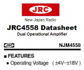
Japan Radio invented the JRC4558 (JRC was Japan Radio Corp before they changed it to NEW Japan Radio (NJR).
Digikey sell a Texas Instruments copy called RC4558 and a new Japanese company makes a copy of the JRC4558. They say
IT IS NOT FOR NEW DESIGNS.
Japan Radio invented the JRC4558 (JRC was Japan Radio Corp before they changed it to NEW Japan Radio (NJR).
Digikey sell a Texas Instruments copy called RC4558 and a new Japanese company makes a copy of the JRC4558. They say
IT IS NOT FOR NEW DESIGNS.
Attachments
-
 12 KB Views: 2


")


