Signal Generator Amplifier DIY

Thread Starter

Frank Bolleri

Joined Sep 23, 2023
77
Hello all,
making experiments on Control Dyson DC35 Multifloor vacuum cleaner motor I discover that exists labs devices like Siglent SPA1010 or TS250
Searching, I found this article Low Cost Function Generator Amplifier DIY where is described an hack to obtain a similar device using a popular board equipped by IC OPA541 .
I have purchased that board and it works well out of the box, AC coupled; but doing the hack described to transform it into a DC coupled, after some minute of usage it fail (driving a little 3V motor in PWM...).

In any case, I was fascinated by the idea to control power devices using signal generator and I was stimulated to design a personal solution for a similar device.
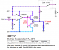
This is my diagram:
Screenshot 2023-10-15 at 13.20.14.png

I will post also the link of Falstad Online circuit simulator, the one I have used to design it.

Because I am a complete newbie, I am pretty sure it is too simple and contains some stupid errors.
In next days, when I will have some time, I will try to build and test it.

Meanwhile I will be happy if someone with experience can give me some suggestion and help me to learn.

Francesco
 
Last edited by a moderator:

Audioguru again

Joined Oct 21, 2019
6,826
Your schematic is a negative image with its parts too far apart.
The LM358 will explode with your 60V supply. Its maximum allowed supply is 32V.
Your Mosfets are used as source followers that have a huge input voltage loss of 10V each.
17A is a current, not a power. 2V peak into 4 ohms is a peak current of 0.5A and a peak power of only 1W.
 

Thread Starter

Frank Bolleri

Joined Sep 23, 2023
77
Thanks for your review.

Your schematic is a negative image with its parts too far apart.
I am sorry for negative, I have copied from the simulator, which is rendered in that way.
For the distance, I feel confortable to design in that way using that tool.
There is some convention to respect for this?

The LM358 will explode with your 60V supply. Its maximum allowed supply is 32V.
I was confused reading the datasheet of LM358 - I did not get that 32 V is total range and in dual power supply means +/- 16 V.
Thanks, if I will build it, I will stay in the range.

Your Mosfets are used as source followers that have a huge input voltage loss of 10V each.
I am not able to understand what you mean. Can you teach me about this?

17A is a current, not a power.
I know 17A is a current and not a power - why you recall me on this point? What I do wrong?

2V peak into 4 ohms is a peak current of 0.5A and a peak power of only 1W.
Ok, but I don't understand the point. Can you explain better?

But at the end, refining the power supply range, it will work?
I tell I am a newbie...

Thanks
Francesco
 

Audioguru again

Joined Oct 21, 2019
6,826
The datasheets for the Mosfets show that they need a Vgs of 10V for each of them to turn on.
Why do you use a +30V and -30V supply for the amplifier that produces an output of only 2V peak?
 

Attachments

Thread Starter

Frank Bolleri

Joined Sep 23, 2023
77
The datasheets for the Mosfets show that they need a Vgs of 10V for each of them to turn on.
Why do you use a +30V and -30V supply for the amplifier that produces an output of only 2V peak?
Because I am a newbie and I have to learn: I don't know nothing about Vgs value.
Thanks for your feedback - when I will have some time I will try to study and learn about this error.

Please note that the values +30V and -30V from power supply, 1Vpp (+ 1V offset) from signal generator and the LOAD = 4 Ohm are arbitrary values I have inserted just to start the simulation.

Thanks,
Francesco
 

Audioguru again

Joined Oct 21, 2019
6,826
Most people learn about electronics in a university with a professor and a few good textbooks.
They read all the details of a transistor on its datasheet provided by its manufacturer without any guessing.
 

atferrari

Joined Jan 6, 2004
5,007
Most people learn about electronics in a university with a professor and a few good textbooks.
They read all the details of a transistor on its datasheet provided by its manufacturer without any guessing.
So Audioguru, what we will do with Frank? Hanging him in the main square at dawn?
 

AnalogKid

Joined Aug 1, 2013
12,094
after some minute of usage it fail (driving a little 3V motor in PWM...).
Using an analog amplifier to drive a motor with PWM is not a good idea. A lot of heat is dissipated in the output transistors, partly because most analog amplifiers are not good at producing a squarewave, which is basically a digital signal.

Better to drive transistors in a switching circuit.

ak
 

Thread Starter

Frank Bolleri

Joined Sep 23, 2023
77
Hello all,
I am truly sorry that I have caused a bitter discussion among you due to my ignorance.

I will try to learn something from the suggestions I get from some of your posts above before update my schematic.
I realize reading here that maybe is better I don't try to run it as is, in order to avoid the explosion of my home:)
But I kindly ask you: was I wrong to sign up to this forum? Is it intended only for professionals?
If so, I apologize because I didn't understand and I will unsubscribe.

Thanks,
Francesco
 

BobTPH

Joined Jun 5, 2013
11,492
But I kindly ask you: was I wrong to sign up to this forum? Is it intended only for professionals?
If so, I apologize because I didn't understand and I will unsubscribe.
No, everyone is welcome here. My comment was not directed at you. It comes from frustration with some posters who just cannot grasp the simplest concept. And even they are welcome. I will try to answer anyone’s questions, but often give up after several posts that have no impact.
 
Top