Short Circuit

Thread Starter

Transatlantic

Joined Feb 6, 2014
44
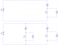
I was watching a video recently in which the author said that when you have a circuit like the following :

upload_2015-5-31_22-23-32.png

Into which you introduce a short :

upload_2015-5-31_22-24-1.png

Then no current flows through the second branch, and the LED won't be lit.

This confused me a little as I pictured the 'short' just being a resistor with a very low value, and figured that the same amount of current would flow through the second branch as before, and that the LED would stay on. So I tested this with Multi-sim, and the results agreed with what I thought :

upload_2015-5-31_22-28-25.png
Yet in a different package (LiveWire), I get this :

upload_2015-5-31_22-34-16.png

I also tested with LTSpice which seems to give the same results as Multi-Sim. I'm not sure if it's even valid to simulate this circuit as in the real world stuff will just blow due to the huge currents, but in theory, what would happen?
 

Attachments

cmartinez

Joined Jan 17, 2007
8,253
In reality, the current through your very low value resistor (such as a normal wire) will be so high that it will burn and blow like a fuse.
Also, if you're using a battery, the battery will most likely spend all of its available capacity trying to feed that wire, and the rest of the circuit will get very little, if any, current
 

MikeML

Joined Oct 2, 2009
5,444
The simulators are confused because they think a voltage source is ideal, and the voltage source will maintain its terminal voltage regardless of current.

If you want to simulate the reality, you must tell the simulators that their voltage source has some series resistance. In LTSpice, that is one of the settable attributes of a voltage source. In other simulators you may have to put the series resistance in explicitly.
 

WBahn

Joined Mar 31, 2012
30,058
Simulators work with models of real components and, thus, the simulation results are only as accurate as the models. For many applications, the models can be pretty simple and still provide results that match the real circuits very closely. But when you start pushing the limits of those models, the simulation results can quickly become rubbish. Your "LiveWire" package appears to be incorporating some internal resistance to the battery. Using the 44.98mA in the first simulations as a reference, it appears they are using 0.1Ω.
 

WBahn

Joined Mar 31, 2012
30,058
The LiveWire results in the second simulation are not very self-consistent. They may be assigning non-ideal parameters to the ammeter and voltmeter circuits, but I suspect it is probably more related to roundoff error in the basic simulation engine.
 

crutschow

Joined Mar 14, 2008
34,445
In the theoretical simulation, the battery has no resistance and so will provide its rated voltage even at very near infinite currents.
In real life the battery has a resistance and its voltage will thus be divided between that resistance and the "short" resistance, with both acting as a two resistor voltage divider network.
So whether the LED lights or not depends upon whether the relative resistances are such that there is enough voltage across the short resistance to exceed the normal forward bias voltage of the LED.

What you have discovered is that a simulation is only as good as the models you use (and your understanding of the models).
Thus, for example, an ideal model for a battery can give decidedly unrealistic results.
 

MikeML

Joined Oct 2, 2009
5,444
Here is a simulation that is a bit closer to reality...

I choose to model the battery as a 9V ideal voltage source in series with a 4Ω internal resistance, meaning it can deliver a finite short circuit current of about 2A.

I choose to model the short circuit with a time-dependent switch, which turns on at 1 second into a 2s simulation run. It has a specified resistance of 1mΩ when closed; by simulator default, ~1GigaΩ when open.'

Now follow along to see what happens to V(b) with the short absent or present... Note that it starts a bit less than 9.0V and drops to ~0V when the switch closes. The reason that it is a bit less than 9V is because of the IR drop across the battery internal resistance even with the small (~25mA) LED current.

Note what happens to I(R1) after the switch closes.

Finally, notice that the maximum current through the simulated short circuit (the switch) is determined by the battery's internal resistance R2.

228.gif
 
Top