Series LR Circuit

Thread Starter

RdAdr

Joined May 19, 2013
214
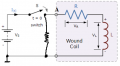
Consider the circuit in the attachment.

If the switch has been open for a long time, then the potential at point A is 0V and the current is 0A. When the switch is closed, the potential at point A is Vs and current starts to flow.
So instead of the Vs voltage source and the switch, I can use a voltage source that is 0V before t=0, and then at t=0 it becomes Vs. So the input voltage is :
v = Vs*u(t), where u(t) is the step input voltage
And thus I can analize this circuit with the Laplace method or other methods of solving differential equations.

Now, my problem.
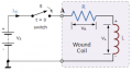
If the switch has been closed for a long time, then the potential at point A is Vs and the current is maximum. When the switch is opened, the potential at point A is not ground. So instead of the Vs voltage source and the switch, I cannot use a voltage source that is Vs before t=0, and then at t=0 it becomes 0V:
v=-Vs*u(t)+Vs
So, how can I analyze this circuit?
 

Attachments

Last edited:

Veracohr

Joined Jan 3, 2011
772
Consider two things:

1. What is the current through the resistor after the switch is opened?
2. What inductor equations do you know that might apply here?
 

crutschow

Joined Mar 14, 2008
34,432
When the switch is suddenly opened in an ideal circuit then you have a singularity, since the current will try to continue but it has nowhere to go, causing the voltage to rise to infinity.
In a real circuit the voltage will rise until the stray circuit capacitance stores the inductive energy (called a resonant charge).
There will likely be an arc across the switch, if it is mechanical, before this peak voltage is reached.
If it is a fast electronic switch, such as a transistor, then it may be damaged by this voltage.
That voltage is called an inductive spike and is normally suppressed by some sort of snubber circuit.

If you want to observe the current decay when the voltage is removed then you need add another switch to ground to provide a current path when the series switch opens (or simply suddenly set the voltage source to 0V).
 

WBahn

Joined Mar 31, 2012
30,058
You might put a resistance, R, from the right side of the switch to ground. When the switch is closed this will have no impact on the current waveform in the R-L branch, but when you open the switch the current will have a place to go. Use different values for R to see the tradeoff between the peak voltage and the amount of time it takes for the current to decay away.
 

Thread Starter

RdAdr

Joined May 19, 2013
214
Ok. Let's say I put a resistance RA from the right side of the switch to ground like in the attachment.

So, if the switch is closed the current rises slowly to the maximum value. And the inductor's voltage decreases slowly to 0. This is the usual series LR circuit.

If the switch is opened, then the resistance between the switch and the ground appears. And, thus the current through the inductor is:
i=V/(R+RA)*exp[(-(R+RA)/L)t]

Ok. And if this RA goes to infinite (because this is what interests me) then the current goes to 0, for t different than 0.
If t=0, and if RA goes to infinite, then I have exp(-infinite*0).

What happens at t=0?My calculus skills are very rusty. What is the limit when RA goes to infinite of that exponential evaluated at t=0?

And another question. Lets say that RA is not infinite but a very big resistance (the resistance of air). Then the voltage drop across it is:
v=-RA*i =-RA* V/(R+RA)*exp[(-(R+RA)/L)t]
This should be a very high voltage. And because of this we use flyback diodes.
But if RA is very big, then RA/(R+RA) is very close to 1. So the voltage is:
v=-V*exp[(-(R+RA)/L)t]
At t=0, this voltage is -V. Then it decays to 0.
Where is that big voltage for which we need flyback diodes?


LATER EDIT:

Ok. I solved the problem. Instead of putting a resistance between the switch and the ground, I put a resistance between the terminals of the switch. And because the resistance in the circuit suddenly increases when the switch opens, the voltage across it becomes:
v = -RA/R*Vs at t=0 and then it decays to Vs at t=infinite
So I can see clearly that because the air resistance is very large, then the voltage spike across the switch is very large => arc
Thus, we need the flyback diode.
Also, from the equations that I derived, I can see clearly what happens when RA goes to infinite (Dirac deltas appear).

Thanks.
 

Attachments

Last edited:

Jony130

Joined Feb 17, 2009
5,488
Let as assume V1 = 10V, L1 = 100mH , R = 10Ω and RA = 1MΩ.
Know if we closed the switch current rises slowly to the maximum value. The time constant is equal to L/R = 0.01s=10ms so after t=5*10ms = 50ms
The current in the coil reaches the value IL = 10V/10Ω = 1A
http://www.electronics-tutorials.ws/inductor/lr-circuits.html
Now if we opens the switch, the coil do not like sudden change in current. Coil demands the current to keep flowing in the same direction as previously flowing (1A). So to oppose this change in current the EMF will be generated across the coil.
And this voltage is equal to VL = - 1A * 1MΩ + 10Ω ≈ -1 000 000 V = -1MV and this voltage and current will decay with time constant L/R = 0.1H/(RA +R).
 
Last edited:

MrAl

Joined Jun 17, 2014
11,474
Hi,

Yeah the equation looks like this:
v=I*R*e^(-t*R/L)

where I is the initial current, and at t=0 we have:
v=I*R

so that voltage can be high to start if that second R is a high value. If R goes to infinity (open) then the voltage does too, for an infinitesimally short time.
 
Top