Sequential 194 Reverse Polarity or 3157 Switchback Led Turn Signals

Thread Starter

Ziggylittles

Joined Jul 2, 2017
36
Hi everybody and thank you for any and all helpful input,

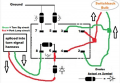
For those unfamiliar with switchback led's, they are led's with 2 different colors they can switch back and forth between commonly used in a white/amber application for vehicle running lights/turn signals. Most are 3157, 7443, or 1157 which allows ground, and 2 different power inputs for the 2 different colors. I have those currently in my parking light and fog light housings on my truck, and I'd like to add a set of switchbacks to cab roof lights. The housings accept a 194 bulb. With 194's being only a 2 input bulb, they switch between amber and white by reversing the polarity. A thread on a different forum provided a useful diagram using dpdt relays. I'll include the diagram in an attachment. I have two things I don't understand though. First, I'd like the lights to be sequential turn signals. There are 5 lights across the roof like so: 1 2 3 4 5. With the right signal activated it would light 3 amber - 2 amber - 1 amber, then all back to white (or off if parking lights are currently off). The left signal would go 3 4 5 amber respectively. Hazard lights would start from 3 and sequence outwards both ways. What I'm unsure of is first how to create this sequencing effect and how to safely add middle light number 3 to both sides.

There is another thread on this forum regarding these bulbs but in a different application. it can be found here: https://forum.allaboutcircuits.com/...it-plus-more-relays-capacitors-diodes.127528/

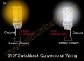
If this proves to be not reasonably possible, my other idea is to bore out the light housings large enough to accept a 3157 bulb and hardwire the bulbs as there wouldn't be enough room for a socket. The wiring with 3157 bulbs would be would be easier I imagine, as there is no reverse polarity to deal with. Whether white (minor) is on or off, amber (major) takes precedence when activated, so the middle bulb could be tied to both sides with diodes I believe. With this option, I am still unsure the best way to create the sequential effect. I am very excited about this project and think it will be the first of it's kind. Again, thank you to everyone for their time and useful advice to either the 194 or 3157 set ups.
 

Attachments

crutschow

Joined Mar 14, 2008
34,201
This will likely required some building of electronic circuits on a perfboard type breadboard.
Are you up to that?
Have you had any experience with soldering small electronic parts?
 

Thread Starter

Ziggylittles

Joined Jul 2, 2017
36
This will likely required some building of electronic circuits on a perfboard type breadboard.
Are you up to that?
Have you had any experience with soldering small electronic parts?
I'm up for whatever gets this job done. I have basic soldering experience but pick things up quickly, especially with good direction. I've seen your detailed replies on some other posts on here and am very glad you responded.
 

Thread Starter

Ziggylittles

Joined Jul 2, 2017
36
Am I correct in thinking the 3157 use will be simpler? If, so, I'd definitely prefer to use them. They will also be brighter and fill out the housings better due to their chip arrangement.
 

crutschow

Joined Mar 14, 2008
34,201
Am I correct in thinking the 3157 use will be simpler? If, so, I'd definitely prefer to use them. They will also be brighter and fill out the housings better due to their chip arrangement.
Certainly the circuitry would be simpler with no requirement to reverse the polarity and the two can be lit independently.
Whether white (minor) is on or off, amber (major) takes precedence when activated,
I'm not sure I understand that about the 3157.
Does sending current to amber shut off current to white?
 

Thread Starter

Ziggylittles

Joined Jul 2, 2017
36
Certainly the circuitry would be simpler with no requirement to reverse the polarity and the two can be lit independently.
I'm not sure I understand that about the 3157.
Does sending current to amber shut off current to white?

Ok great, let's move forward with the 3157's then.

To maintain correct terminology, amber activation does not shut off white's current to the bulb, but if both circuits are activated, the bulb will shine only amber.

There are two types of dual circuit switchback bulbs.

The type I use is type 1.

Type 1 is white for running lights, and once the turn signal is activated alternates white-amber-white-amber until the turn signal is deactivated.

Type 2 is white for running lights, but by using some sort of delay unit on the white circuit, flashes amber-off-amber-off when the turn signal is activated and returns to white after the turn signal is deactivated.

I hope this is helpful clarification, as we do not need to worry about activating or deactivate white at all. The white circuit will be attached to the rest of the running lights. The amber circuit is completely separate and will function the same regardless of whether the running lights are on or off.
 

crutschow

Joined Mar 14, 2008
34,201
So then all we need is a sequencer for the amber lights activated by either the left or right turn signal, is that correct?
No need to worry about the park lights, right?

For the 3157 bulb is the common grounded and you apply 12V to the desired LED to light it?
Or do both LEDs have separate wires?
How much current do the amber LEDs take?

Do you want the sequence to occur at the turn-signal blink rate or faster?
 
Last edited:

Thread Starter

Ziggylittles

Joined Jul 2, 2017
36
So then all we need is a sequencer for the amber lights activated by either the left or right turn signal, is that correct?
No need to worry about the park lights, right?

For the 3157 bulb is the common grounded and you apply 12V to the desired LED to light it?
Or do both LEDs have separate wires?
How much current do the amber LEDs take?
Correct, no need to worry about parking lights.

Both circuits share a ground wire when the bulb is in a socket, but the bulb itself has 2 separate ground prongs as pictured in the attachment featuring images of both sides of the bulb. Notice the image says conventional wiring. Certain vehicles use "CK 3157" bulbs and sockets with different wiring. This is not the case here.

I'm not sure about the power draw, I'll have to test tomorrow.

Currently, I have 2 of these bulbs per side and I know the power draw is below that of a single incandescent as is stock. An incandescent 3157 draws 8.3 watts I believe when activated as a turn signal.

I'd imagine using a relay for the roof lights would be best, as the additional load of 3 more bulbs may surpass the stock incandescent draw.

I currently have cab lights featuring 3 single white leds per housing and those are powered by a 40/30amp relay. I can just reuse that wiring for the white circuit.

I have more of those 40/30amp spdt relays laying around that I can use for the amber circuits unless there is a better way.
 

Attachments

Thread Starter

Ziggylittles

Joined Jul 2, 2017
36
I would like the full sequence to be complete with each flash of the turn signals. As the side marker and fog lights flash amber-white-amber white, these will sequence 3-amber 2-amber 1-amber, all white, 3-amber, 2-amber 1-amber, all white.

The above is an example with the running lights on, as I always have them on when driving. If the running lights were off, the side markers and fog lights flash amber-off-amber-off and the roof lights would go 3-amber, 2-amber, 1-amber, all off.

With a full sequence each turn signal flash, the sequence will have to be pretty fast.
 

crutschow

Joined Mar 14, 2008
34,201
I was thinking of using MOSFETs to control the sequence LEDs so that's why I asked about the current.
With a full sequence each turn signal flash, the sequence will have to be pretty fast.
Speed isn't the problem, but how repeatable and constant is the turn flash time?
Does it vary with temperature or battery voltage?
The clock for the sequence will need to be adjusted so that one sequence will occur just within one flash time.
If there's any variation in the flash time, then the sequence may finish too soon, or not finish before the next flash.
 

Thread Starter

Ziggylittles

Joined Jul 2, 2017
36
I haven't ever checked for consistency in flash time, but the circuit is entirely LED including the turn signals on the front, in the rear, and the indicators in the instrument cluster. Additionally, the flasher relays for the turn signal and hazard lights are both "no load electronic flashers". They are meant to provide a fixed rate flash when LED's are used in turn signals as the low power draw of leds compared to incandescents can make standard flasher units flash slow and/or not at all (or fast when the relays have built in bulb failure warnings).

With these fixed rate flasher relays and all LED bulbs I believe the flash rate should be consistent enough regardless of battery voltage or temperature, with any variance being negligible. Also, my dual optima red top batteries usually maintain relatively consistent voltage besides in extreme cold when the engine's grid heater cycles for a few seconds at a time while warming up.
 

crutschow

Joined Mar 14, 2008
34,201
I would like the full sequence to be complete with each flash of the turn signals.
So one way is that the sequence would be free running when the turn-signals are flashing, doing one sequence approximately for each flash but would not necessarily be exactly synchronized to the flash.
Does that sound okay?

Or do you want the start of the sequence to always start with the flash?
 

Thread Starter

Ziggylittles

Joined Jul 2, 2017
36
I would really like the sequence to begin and end with the flash. With that many signals everywhere, it would look messy any other way.
 

Thread Starter

Ziggylittles

Joined Jul 2, 2017
36
Correct. A full sequence of the roof lights while the signals are lit amber, All roof lights would turn off when the turn signals flash back to white (or off if parking lights are off), and then repeat.
 

Thread Starter

Ziggylittles

Joined Jul 2, 2017
36
^^**all of the amber on the roof would turn off when the signals flash back to white** , resulting in them also flashing back to white if parking lights are on.

Again, we should not need to worry about the white circuit at all.
 

Thread Starter

Ziggylittles

Joined Jul 2, 2017
36
And yes the flash sequence does appear to be an even 50/50 split of amber and non amber time.

Please correct me if I'm wrong, but the way I see it, it makes sense that we only need to program 1 sequence and do not need to worry about any repeating at all. The amber circuit turning on and off should be able to activate a single cycle each time and will cease on its own during the non-amber flash. We don't have to program any type of pause and/or repeating cycle because it will be switched on and off with each flash, no?
 
Top