A Classic Problem with JK Edge Flip-Flop

Thread Starter

richard_w

Joined May 20, 2025
11
I encountered this question when leanring JK Flip-Flop.

The flip-flop application circuit is shown in Figure 1. Given the waveforms of the clock pulse CLK and the reset signal RD', draw the waveforms of the flip-flop states Q0 and Q1. Assume that the initial state of the flip-flop is 0.
1747720366440.png
1747720413582.png
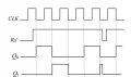
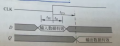
Can someone please explain how to do it?

MOD NOTE: Moved to Homework Help.
 
Last edited by a moderator:

WBahn

Joined Mar 31, 2012
32,703
Welcome to AAC.

You need to show your best attempt to get as far as you can. That puts us in a much better position to help you identify and correct whatever your current stumbling block is so that you can proceed.
 

meth

Joined May 21, 2016
298
You know the function of the flip flop right? The truth table?
You have the input values for the first clock impulse.

Make a new table where you write the outputs depending on the inputs for each pulse on the clock until you reach the reset.
So we need a table with clock 1, 2, 3, 4 and 5.
The output of the 1st clock is the input of the 2nd!!

Do the table, post it here and we can talk about it.
 

Thread Starter

richard_w

Joined May 20, 2025
11
1747722273112.png

This is what I got, I think since Rd' is 1 which means the reset is off, so It should toggle every descending edge.
 

WBahn

Joined Mar 31, 2012
32,703
View attachment 349576

This is what I got, I think since Rd' is 1 which means the reset is off, so It should toggle every descending edge.
Look carefully at the circuit and what signals are driving the JKFF inputs.

Draw a table showing what the J and K inputs are for each FF and then, at each falling clock edge, use the inputs prior to the clock edge to determine what that FF's output becomes.

Separately, go back and review what happens when the reset signal is asserted (taken LO). There's a reason that they asserted it away from the clock edges.
 

Thread Starter

richard_w

Joined May 20, 2025
11
You know the function of the flip flop right? The truth table?
You have the input values for the first clock impulse.

Make a new table where you write the outputs depending on the inputs for each pulse on the clock until you reach the reset.
So we need a table with clock 1, 2, 3, 4 and 5.
The output of the 1st clock is the input of the 2nd!!

Do the table, post it here and we can talk about it.
1747722705638.png
 

Thread Starter

richard_w

Joined May 20, 2025
11
Look carefully at the circuit and what signals are driving the JKFF inputs.

Draw a table showing what the J and K inputs are for each FF and then, at each falling clock edge, use the inputs prior to the clock edge to determine what that FF's output becomes.
1747723803418.png
 

meth

Joined May 21, 2016
298
Before the first clock Q0 and (I guess ?) Q1 is 0.
JK flip flops work like this:
1747726606128.png
So if 0 and 0, state is unchanged, if 1 and 1 state is inverted, 0 and 1 is 0, and 1 and 0 is 1.
The table you draw is good, it has all the states you need, you just need to review the values.
 

WBahn

Joined Mar 31, 2012
32,703
Before the first clock Q0 and (I guess ?) Q1 is 0.
No need to guess. The reset to both flip flops is asserted at the beginning of the timing diagram.

Furthermore, the problem statement says to assume that the initial state of the flips flops are zero (though this is redundant, given the explicit reset shown in the timing diagram).

JK flip flops work like this:
View attachment 349590
So if 0 and 0, state is unchanged, if 1 and 1 state is inverted, 0 and 1 is 0, and 1 and 0 is 1.
The table you draw is good, it has all the states you need, you just need to review the values.
Note that the JKFF used in the given circuit is negative-edge triggered. Your table is for one that is positive-edge triggered.

An easy way to remember the truth table is that if J and K are tied together, you have a T-type flip flop. It toggles if the input is HI and holds its current state if LO. If the inputs are different, then you have a D-type flip flop with the output following the J input (whether it follows the J or the K can be remembered by either noting that it follows the alphabetically-first input, or that 'D' is closer to 'J' than it is to 'K').
 

Thread Starter

richard_w

Joined May 20, 2025
11
1747729377746.png
This is the answer included by the author of the book. Can someone explain why Q1 is 1 in the second falling edge rather than the first one? and why is the Q0 not 1 in the third falling edge?
 

Attachments

meth

Joined May 21, 2016
298
Previous state of Q1 is 0, on the first FF, on K input you have 1 constantly, and on the J input you have Q1 inverted. So you have two 1's, which will cause Q1 to change state. (for the second falling edge).

Set your start values correct, for each next clock, J0 is Q1 inverted and J1 is Q0. Look at the states and the truth table and update your outputs.
If you dont set your start values correctly you gonna mess everything.

Since you have the graphic solution, write that into the table and observe, you gonna figure it out.
 
Last edited:

meth

Joined May 21, 2016
298
Listen.
After the reset before the first clock: (I will refer to the values as J1, J2,... Not J0, J1 and so on)

Q1 is 0 and Q2 is 0.
J1 is 1 (Q2 inverted) and J2 is 0 (Q1)
K1 and K2 are 1.

!!! CLOCK NO. 1 !!!
In your table first you calculate the outputs!!!!

J1 was 1, K1 was 1, this mean Q1 after the clock will be 1 (previous state is inverted because two 1's)
J2 was 0, K2 was 1, Q2 will be 0.

After we have the updated Q1 and Q2, we update the rest of the values for the next takt:
J1 will be 1 (Q2 inverted), J2 will be 1 (Q1).
K1 and K2 are 1.

!!! CLOCK NO. 2 !!!
First we calculate the outputs.
J1 was 1, K1 was 1, Q1 will be 0 (prev state inverted).
J2 was 1, K2 was 1, Q2 will be 1 (prev state inverted).

Other values for next clock:
J1 will be 0 (Q2 inverted), J2 will be 0 (Q1).
K1 and K2 are 1.

!!! CLOCK No. 3 !!!

Both flip-flops have 0 on J and 1 on K, both outputs Q1 and Q2 will be 0. (so far this is OK with the graph).

Update J2 and K2 (as you see we have same state as the beginning, so these states would change periodically, or, as you can see in your case, there is new reset after the next clock).

I hope this is understandable and I did not make any mistake.
So it is very important to begin correctly.
BEFORE FIRST CLOCK: Q1 is 0, and Q2 is 0 !!!! This means at the moment of the clock J1 will be 1 and J2 will be 0 !!!!!
AFTER THE FIRST CLOCK: FIRST UPDATE Q1 and Q2!! MOST IMPORTANT! After that update J1 and J2 according to the new Q1 and Q2. Then clock again, update Q1 and Q2 according to the last values, then update J1 and J2.
 

WBahn

Joined Mar 31, 2012
32,703
View attachment 349594
This is the answer included by the author of the book. Can someone explain why Q1 is 1 in the second falling edge rather than the first one? and why is the Q0 not 1 in the third falling edge?
Because the J singles are not what you are insisting that you want them to be. Yet again, look very carefully at where each of those signals comes from.

Add the two J signals to the timing diagram. Don't make a table, just add them to the timing diagram.
 

Thread Starter

richard_w

Joined May 20, 2025
11
Listen.
After the reset before the first clock: (I will refer to the values as J1, J2,... Not J0, J1 and so on)

Q1 is 0 and Q2 is 0.
J1 is 1 (Q2 inverted) and J2 is 0 (Q1)
K1 and K2 are 1.

!!! CLOCK NO. 1 !!!
In your table first you calculate the outputs!!!!

J1 was 1, K1 was 1, this mean Q1 after the clock will be 1 (previous state is inverted because two 1's)
J2 was 0, K2 was 1, Q2 will be 0.

After we have the updated Q1 and Q2, we update the rest of the values for the next takt:
J1 will be 1 (Q2 inverted), J2 will be 1 (Q1).
K1 and K2 are 1.

!!! CLOCK NO. 2 !!!
First we calculate the outputs.
J1 was 1, K1 was 1, Q1 will be 0 (prev state inverted).
J2 was 1, K2 was 1, Q2 will be 1 (prev state inverted).

Other values for next clock:
J1 will be 0 (Q2 inverted), J2 will be 0 (Q1).
K1 and K2 are 1.

!!! CLOCK No. 3 !!!

Both flip-flops have 0 on J and 1 on K, both outputs Q1 and Q2 will be 0. (so far this is OK with the graph).

Update J2 and K2 (as you see we have same state as the beginning, so these states would change periodically, or, as you can see in your case, there is new reset after the next clock).

I hope this is understandable and I did not make any mistake.
So it is very important to begin correctly.
BEFORE FIRST CLOCK: Q1 is 0, and Q2 is 0 !!!! This means at the moment of the clock J1 will be 1 and J2 will be 0 !!!!!
AFTER THE FIRST CLOCK: FIRST UPDATE Q1 and Q2!! MOST IMPORTANT! After that update J1 and J2 according to the new Q1 and Q2. Then clock again, update Q1 and Q2 according to the last values, then update J1 and J2.
This is very helpful! THANK YOU!

I kinda understand and get a better solution. If my understanding is correct, I believe I can conclude two rules:

#1: JKFF0 toggles when falling edge comes. IN ONE EDGE, THERE CAN BE NO SECOND JKFF1 TOGGLE. But it can change the value of Q0 & J1.(see graph 1 about the tsu th tco)

#2: Rd can reset the JKFF any time in the pulse cycle, and in the same cycle, once it is reset, it can not toggle again.

1747828059018.png

graph 1: Tsu Th & Tco (https://commons.wikimedia.org/wiki/File:FF_Tsetup_Thold_Toutput.svg)
 

Attachments

meth

Joined May 21, 2016
298
1747830539649.pngthis is the symbol for trigger on falling edge. Without the circle, only triangle, it is trigger on rising edge.
On trigger update only outputs (Q1, Q2, Q1' Q2') based on the state of the inputs. After that, if the output of one FF is input on some other point, then you update that.

Reset is like "master" input, or highest priority input (all this should be included in a datasheet for the specific chip that you would be using, but in homework like this, reset is No. 1 priority), and if on trigger the reset is active, the outputs would be set on whatever is stated in the datasheet in a reset scenario, regardless of the other inputs.
 
Top