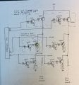
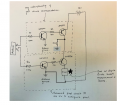
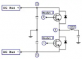
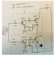
Thank you! You also asked me why the 2N3096's are in series. Here is a drawing of the larger circuit I would like to make that includes multiple pixel circuits. The one I made today only include two (one to supply 12 volts and the other to power the pixel) But in reality there would be many more of both:
It would have been better for me to share this at the start.
Many thanks,
Louise
Thanks for the suggestion and I will read more into the 74HCT86. I haven't used one before. A quick question, do both the 74HCT86 and the wave from the oscillator go to the pixel and would this be the arrangement you suggested before - connecting to both to either side of the ITO glass? Meaning, the 74HCT86 to one face and the oscillator to one face?
Thank you!
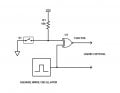
The square wave oscillator generates a 50 % duty cycle (not critical) at any frequency (100 Hz to 1000 Hz, not critical).
You can use a 555-timer, any logic circuit oscillator, or even the Arduino.
The logic gate shown in the circuit diagram is an Exclusive-OR gate, a.k.a. EOR or XOR gate. It performs the phase inversion when the switch S1 is not closed, i.e. the control input to the XOR gate is HIGH.
The generic part number is 74xx86.
Any of these will do:
7486
74LS85
74C86
74HC86
74HCT86
If you use 7486, or 74LS86, change R1 to 4.7 kΩ.
Also CD4070, MC14070 will work.
If you choose MC14070 you can extend the supply voltage to +18 V.
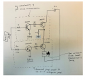
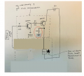
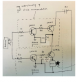
Thanks for your help with this, sghioto. I have made both circuits but unfortunately, the pixel remains with 3volts across it and never drops to zero volts. As a result it stays black. These are the circuits I have made (with the 2N3906 in series and without):
I am not really sure where to go with this because I guess I don't understand how the base of the 2N3906 rises to a higher voltage than 0.
Any further ideas would be really appreciated.
Best wishes,
Louise
Doesn't make sense.
Are you positive the circuit is wired correctly?
Also try adding a 10K resistor from the base to the emitter of the 2N3906.
The 12 volt negative needs to be connected to the Arduino ground.
Doesn't make sense.
Are you positive the circuit is wired correctly?
Also try adding a 10K resistor from the base to the emitter of the 2N3906.
The 12 volt negative needs to be connected to the Arduino ground. View attachment 353760
Thanks again for your reply. Yes, maybe there is something fundamentally wrong with the actual circuits I made. Your suggestions don’t work on a breadboard nor when soldered, so I will try again tomorrow from scratch.
Maybe the junctions I solder are bad.
Thanks for confirming the ground location too. I did not have them arranged like this: the 12v negative connected to the Arduino.
Thanks and have a lovely evening!
I would try this test first with Vcc at 5 V.
The two square wave signals from the Arduino are the same for crystal = OFF, and out of phase for crystal = ON.
Edit: You can also skip this circuit entirely and connect the liquid crystal directly across two pins of the Arduino.
I believe that's is the problem.
Latest suggestion: add a 10K resistor to ground on the collector of all the 2N3906 transistors.
EDIT: 2N3906 transistors
I would try this test first with Vcc at 5 V.
The two square wave signals from the Arduino are the same for crystal = OFF, and out of phase for crystal = ON. View attachment 353763
Cool! Thank you and yes, I’ll try this too. Is there a reason why 2N3094 has been selected over 2N2222? Just so I understand for the future.
Thank you also for your earlier information. I think I will need to read more around the subject to understand but it’s quite a long research project, so I have time! It’s also useful to know more about how the actually work, rather than mimicking the out come, which is what I’m kind of doing now.
I believe that's is the problem.
Latest suggestion: add a 10K resistor to ground on the collector of all the 2N3904 transistors. View attachment 353765
Cool! Thank you and yes, I’ll try this too. Is there a reason why 2N3094 has been selected over 2N2222? Just so I understand for the future.
Thank you also for your earlier information. I think I will need to read more around the subject to understand but it’s quite a long research project, so I have time! It’s also useful to know more about how the actually work, rather than mimicking the out come, which is what I’m kind of doing now.
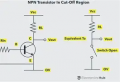
I use 2N3904 because I have lots of them. Just about any NPN BJT will work. The transistor is operating as a switch. It is either OFF or ON. The major parameters of concern here are the maximum operating voltage, current, and power dissipation.
When the base-emitter voltage is less than 0.5 V, the transistor is OFF. the output voltage is Vcc.
When the base-emitter voltage is greater than 0.7 V the transistor is ON, the output voltage is close to 0 V.
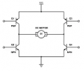
If you replace load resistor RL with another transistor switch, you have what is known as a half H-bridge.
A full H-bridge circuit would look something like this:
Now you can imagine how an H-bridge is used to reverse the current flowing through the motor.
In your case the liquid crystal replaces the motor. By having both sides of the liquid crystal actively driven you can reverse the polarity of the voltage applied across the liquid crystal. The XOR circuit I showed you does the same thing.
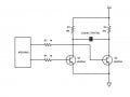
Hi Everyone, I just wanted to say thank you for your help last week. I managed to get the individual circuit working at 12v using the following circuit, which is great!
So, thanks!
I just had one final question, please?
If the 2N2222 doesn't work at 12v and does at 5v, what would you say is the limit for the number of volts that can be used with that transistor? I'm looking for a kind of "rule of thumb", if it exists.
Many thanks and have a good week!
I just had one final question, please?
If the 2N2222 doesn't work at 12v and does at 5v, what would you say is the limit for the number of volts that can be used with that transistor? I'm looking for a kind of "rule of thumb", if it exists.
Many thanks and have a good week!

 Facebook
 Google
 GitHub
 Linkedin