Scoreboard Project Cont;

Thread Starter

Oxbo Rene

Joined Feb 20, 2009
201
No, No, No, Kit and big LEDs are common ANODE .....
But,am really in trouble now !
Was in there ironing the layout onto the copper board then, CRACK ! !
Forgot to iron on safe surface, was ironing on the wife's 4ft circular glass table top, yep cracked it real good !
That'll be another hundred bucks probably.
Actually, she is napping over here on the couch and doesn't know it yet. I could rotate it around to the wall side and throw a place mat over it.
Then, in a few days when she discovers it and asks me about it, I can just reply Huh ?
I don't know baby, dam, that's odd......
OK, gotta go see if I can get the paper off this thing....
 

SgtWookie

Joined Jul 17, 2007
22,230
Yikes! :eek:

Dang, that's bad news. :(

I usually use a nice flat piece of wood to iron the transfer with. You really have to go over it a bunch of times.
 

Thread Starter

Oxbo Rene

Joined Feb 20, 2009
201
Yep, live and learn.
I guess that's part of the reason I'm somewhat hardheaded as to change.
Have everything I need to get by already figured out, is "safe", so, no wasted time learning new ways of doing the same thing, etc. Something like that....
Just finished doing a second board, have it soaking now.
One real relief is that the acetone wiped the ink right off, that was a pleasant surprise.
I spent some more dedicated time on this one, sure hope it works. Am concerned that I could "over-do" it.
Oh yeah, how about running it through the printer a second time?
Was thinking about doing that, but, paper comes out somewhat curled on the ends, could do it but would take a moment getting it back in the proper position, etc....
Yes, I read that about having it sizzle. I decided to let this one cool on it's own (assuring the ink dries good) before putting in water.....
 

Thread Starter

Oxbo Rene

Joined Feb 20, 2009
201
Alright;
Got the new board etched.
One laser printer = $107.00
One Dinning room table top = $167.00
One etched board = $274.00 LOL.....
Only lost around four pads and a few partial traces, which
I added in with magic marker...
When I finally got the paper off, there was a layer of plastic film
that was left in several small areas. I took my hobby craft knife
and flaked it off but didn't try to remove it from the traces, etc.
Was a bit tedious but seems like everything is going to work.
Traces = .025 Width
Pads - 100(X)33
I guess that is about right, etc...
Have a nice day
Oxbo
 

Attachments

Thread Starter

Oxbo Rene

Joined Feb 20, 2009
201
Ok folks !
Finally got the latest board installed.
Everything seems to work fine.
Going to do a little house cleaning with the wires, then, on to putting the "kit" board together, and after that, will have to have a buffer board, and then get to play with those big LEDs.
 

Attachments

Thread Starter

Oxbo Rene

Joined Feb 20, 2009
201
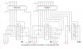
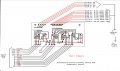
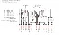
This is my design for the buffer board to isolate the data drive transistors (4) and the data lines to the 7-segment LEDs. Actually, the 8th line is for the DP, of which I plan on just firing them up (one LED display turned upside down to utilize the DP's as colon in the clock,ect).
I noticed that Mr Gibbs did not utilize an open collector chip for the 4 transistor drivers, rather, using just a non-inverting buffer (74LS07).
I figure perhaps those buffers have enough pwr to make the trip across the 10ft cable, however I have decided to utilize an open collector chip (I think Sarge might've suggested it).
Anyway, here it is, and I believe it will suffice quite well.
Still haven't gotten to putting the kit together yet, as I wanted to get this board worked out, since it'll be needed right as I get the kit together, etc, etc.
Have a nice day.
Oxbo
(Hmmmm, just noticed I don't have data input lines matching their outputs = back to the drawing board)
 

Attachments

Last edited:

Thread Starter

Oxbo Rene

Joined Feb 20, 2009
201
Well, have finally run into a problem.
Have gotten the "kit" assembled.
Turn it on, supposed to do self test, first displays the model # (K8035) which it does. Then supposed to say "TEST" , which it displays some eroneous symbols, then is supposed to say "good" which it doesn't, it displays something to the effect of "5 er".
There is an error code list that suggests it displays->
Err 2- Error in Keyboard section.
Err 3- DIP switches in wrong position.
Err 4- Input A is active during self-test, or, input A malfunctioning.
Err 5- Input B is active during self test, or, input B malfunctioning.
I put it through it's paces, the count up works good, the count down works good, the reset works good.
Problem seems to be with the set/run part.
I have looked at the book but cannot find any reference to an input A or B.
when I hit set/run it shows the 5er then goes to zeros and begins blinking, etc.
Only problem I had in assembly was that I got the zener diodes mixed up with the other diodes, had to remove a couple and re install, am wondering if perhaps I might have burned one out, wonder if that would cause the results. However, feel that I did not damage them, but, we know how that goes, etc, etc.
Any suggestions ??????????
Specifically, am wondering just what "inputs A and B are"....
Oxbo
Edit- OK found it A=pin #9 (must be active for auto count to work=external switch) B=pin #8 (must be active for auto count to work=external switch) Found this info on another forum, but don't think it will solve problem, etc....
 
Last edited:

Thread Starter

Oxbo Rene

Joined Feb 20, 2009
201
After playing around with it and picking up some small but important amount of info from the Velleman forum, have concluded that indeed the kit says "good" in it's boot up self test phase. It doesn' t say test, unless I just can't decipher what "test" looks like displayed on 7-segments, but I Definitely can see the "GOOD" as the last part of the self test, so, am pleased.
And have found that I'll need two additional switches for "Begin auto Count Up", and "Begin auto Count Down".
The other count switches are for incremental counting (one at a time).
And have discovered that the count continually cycles right on through zero. One has to utilize a relay with the "equal out" to stop the count.
Man, this little console is already cram packed full of boards and wires!
Hoping I can add the two switches and relay without having to add more Ic's, but it doesn't look too promising.
Will post pics when I get a chance, this working 6 days a week is really getting in the way of my project and my fishing !
Have a nice day
Oxbo
 

Thread Starter

Oxbo Rene

Joined Feb 20, 2009
201
OK, have hit a brick wall ! !
I thought about writing out a long fact filled info report of the problem, but, am just worn out.
Long story short =
Had different leds (little bigger, requires a little more current (DA56-11GWA), but works well with existing circuit, all hooked up on breadboard (to KIt) (was using double LEDS and had the units/10's turned upside down so as to be able to light up the decimals to make a colon)and all worked fine. Went and hooked up kit into console/leds, then things went zonk.
Leds light up but count won't count up/down.
Pwr up seems to work OK, but the thing just won't go, The "Equal-out" LED stays on=meaning it is not counting, etc. Acts like it works but doesn't reflect it in the LEDS.
Have gone through and re-checked all wires, even detached hot wires to each LED and still can't isolate the problem.
I am of the opinion that the PIC16C57 chip has been damaged/deprogrammed somehow.
I really can't find anything wrong other than the possible output of the chip has changed.
I know this is very foreign to you guys at this point.
My question= Anyone know anything as to the particulars/quirks of this chip?
I'm at the point that I am going to have to order another kit, and replace the chip, see if that fixes the problem, etc....
Oxbo
 
Last edited:

SgtWookie

Joined Jul 17, 2007
22,230
Oxbo,
Sorry you're having problems.
Can you get the kit back to it's original state without breaking things? That will help you simplify the problem. If it works without the big display add-on, then you know the area where the problem lies.
 

Thread Starter

Oxbo Rene

Joined Feb 20, 2009
201
Hi Sarge;
Tx's for the comeback.
Yep, will have to take it back to beginning, will take some time.
I am soooo worn out/tired from work and messing with this thing, now the big failure. Actually offered to buy one for my kid, his response = Oh no ! I want this one ! ! !
Just ain't gonna get off the hook, think I'll call it the "Never ending Scoreboard"
Stayed in bed all yesterday, didn't go in to work today, just no energy, flat out dead tired, need a vacation (but, my vacations are a lot of work too, driving all the way to West Virginia and back).
Computer starting to lock up upon boot up, I think my CMOS Batt is going out, boat is broke, replaced water pump on truck today, = the walls are closing in on me EEEEEAAAhhhhHHHh ! ! ! ! ! ! !!
Still, got to mow the da*ned grass ! !
Back's killin me, dogs want their butts scratched, Am nodding off as I type this..........
Other that that, life is great....
I'll get back to ya when I get kit back to point "A", etc..
Have a nice day,
Appreciate it,
Oxbo
 

Thread Starter

Oxbo Rene

Joined Feb 20, 2009
201
OK, Good News ! ! !
Finally having a Sat off, woke up this morning and looked at the mess I haven't had to confront in approx two weeks.
Giving up yet another fishing day, dreading to have to unsolder 40 some odd wires to remove the kit from the console to retest it's working status, I figured I need to do some last minute checking.
I had been thinking that I had also connected up the "tapped off" data lines from the kit to the buffer board, however, I didn't have the buffer board hooked up to V+, thinking that those lines would be effectively opens, etc.
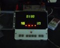
So, as a last ditch effort, hooked up buffer board and kit pwr together and fired her up = WALAAAAAA ! ! Everything WORKED !!!!!!!!!
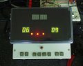
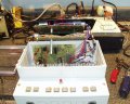
See pics, etc.......
Have got to put it all back together, and finally go on to making the "relay board, and installing the extra push button switches.
Haven't fired up the "colon" LEDs yet as I will just auto fire them at pwr on with resistors and direct connect to V+...
Sorry to admit that all this messing with it has resulted in a lot of "Jimmy-Rigging" and not too proud of the wiring job at this point. Keep putting 3M-5200 sealant on connections to insure wires from breaking off at re-soldered points (long story).
Explanation of why un-powered buffer board prevented LEDs from operating properly would be appreciated, etc......
Anyway, here's the pics......
Oxbo
 

Attachments

Last edited:

Thread Starter

Oxbo Rene

Joined Feb 20, 2009
201
Got a problem.....
Have bread boarded the "relay board" setup and everything works fine "EXCEPT"....
Upon prw-on, kit defaults to 0000 and thus exhibits 5V at E-Out, thus energizing K1.
Having K1 energized disconnects K2 & K3 grounds, thus, they are inoperable.
However, not having K1 energized, everything works as expected.


So, what I need is a "one-time" event that keeps K1 de-energized at pwr-up, from then on (after using the count-up/or/down switches), K1 should operate as designed, even at 0000.
I have some Omron "latching" relays that require (+) and (-) to be reversed in order to change states, but have never played with anything like them.
Not sure how to resolve this problem without becoming super complicated.
I need a simple solution if one exists.
Have only space enough for one more circuit board in the console and that can't be very large. It already has to contain the relays ckt plus an astable 555 "fast count up" circuit.
Any help would be appreciated.....
Oxbo
 

Attachments

Thread Starter

Oxbo Rene

Joined Feb 20, 2009
201
Problem solved, sort of....
First off, this is a "count-down" counter, there won't be any instances where one needs to start an auto count "up" or down from 0000, and the perk is, if he really wanted to, then he'd have to begin from the number "1", rather than "0".
I forgot that this counter also has the "incremental (one digit at a time) count buttons.
I notice that the buttons on the "kit" only produce one pulse at a time, holding it down produces nothing more that the single pulse.
Somehow my parallel wires coming off of them provide me with the "fast up/down" option,
if one continues to hold one of these buttons (my own button connected to the parallel wires) down, the count speeds up, so, no need for seperate "fast-up" circuit.
So, I think I'm OK with all this...
Have a nice day,
Oxbo
 
Last edited:

Thread Starter

Oxbo Rene

Joined Feb 20, 2009
201
OK;
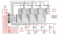
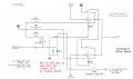
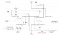
Here's the final schematic, and the PCB layout for the Relay Board.
Could've connected Sw1-3 hot sides together outside of PCB but for clarification, had them connect to PCB.
This is the final board, and everything is working perfectly on the breadboard.
Was hoping to get it all together this coming Sunday but something else came up, perhaps later in the day I'll be able to get some done on it.
Have a nice day,
Oxbo
 

Attachments

Thread Starter

Oxbo Rene

Joined Feb 20, 2009
201
OK Folks !
The "Console" is completed and working just fine !
Called my son up and told him he could come over and pick it up and take it home with him and play with it (Burn-In).
His reply was, OK Dad, will see if I can find the time to get over there this coming weekend.
So much for the last 10 months working on this thing ! !
Still got the second phase to build (Big Board).
I have all the documentation down in a "Word" document (w/Pics), it comes to around 36 megs/32megs zipped.
So, about the only thing I can say is, if anyone wants the stuff, please send me PM or e-mail and I'll shoot it to you
Have a nice day,
Oxbo
 
Last edited:

Thread Starter

Oxbo Rene

Joined Feb 20, 2009
201
Greetings;
Long time, finally back at the scoreboard.
Little console still cooking along just fine.
Am now beginning on the "Big Board".
Looked and looked around and just never could find
a suitable enclosure, so, wound up fabricating my own,
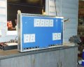
and, looks good, a little weighty but will be fine.
I have gotten the LED support board installed and
now am going to begin with the power supply.
Not sure how much power the whole system will take,
(console runs at 720ma) so thinking of using one of those
little pwr supplies from MPJ rated at 3 amps, I think I'd
be fairly safe with 3 amps.
The power supply will provide all power to both units,
conlole and big board.
My question, do I need a regulated/switching Pwr supply, or
would an unregulated one suffice ??????
Oxbo
 

Attachments

Last edited:

SgtWookie

Joined Jul 17, 2007
22,230
Hi Oxbo,

Get a regulated supply.

I just noticed that you don't have diodes across the relay coils - not so good.

You should add them. Bottom side of the board is fine.
 
Top