Scoreboard Project Cont;

Thread Starter

Oxbo Rene

Joined Feb 20, 2009
201
Is Thevenin's Theorem not in your comfort zone? If it is not, you can review the subject in the AAC ebook.

hgmjr
Ha !
Tx's hgmjr.
At 62yrs old, I will certainly look at it, but, am not as inquisitive as I once was, I generally look for the quick solutions these days, and that's because I find that I'll spend a lot of time on something only to find I hit a brick wall at the end, thus having wasted a lot of time.
Certainly, I desire to find the method to figure something out, such as what I'm working on, but in these days there are so many newer ways of figuring stuff out, such as-> those graphs on the MPSA64 should be the key to figuring out the Ib for that transistor, and from there, devise the correct biasing resistors, etc.
But, it just doesn't seem to work out, or at least I can't figure it out, etc...
Been a long time since I was in the electronics field, and then, I wasn't all that secure and comfortable with what I was doing.
Oxbo
 

hgmjr

Joined Jan 28, 2005
9,027
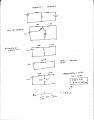
Have a look at the attachment I have provided. You will see that I have used Thevenin to consolidate R1 and R2 into a single resistor with a value of 1363 ohms. I calculated the Thevenin equivalent voltage at around 1.1V. Using a Vbe of 2V (from datasheet), I determine that the voltage at the base is 10V (12V-2V). With the voltage at the base and the Thevenin equivalent voltage, I can determine the voltage across the Thevenin equivalent resistor. This voltage divided by the resistance yields a base current on the order of 6.5 milliamps. Since the MPSA64 has a stated minimum beta of 10000 then you can see that Ib times beta gives you an unrealistic collector current of 65 Amps. Your load only needs a small fraction of that current so that is why sgtwookie and I raised the issue. A base current in the 50 microamp range would be more than adequate. Sgtwookie's resistor values will give a sufficient base current to overdrive the transistor within reason.

hgmjr
 

Attachments

SgtWookie

Joined Jul 17, 2007
22,230
Hgmjr's method is more correct than what I did; I "ballparked" it.

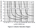
I looked in ONSemi's datasheet at this saturation region chart:


See the -10mA curve? Vce is about 0.8v at about 2.5uA base current, and about 0.72v at 100uA base current.

Vbe will be around 1.8v to 2v, and Vce for the ULN2x04 will be roughly 0.65v at such a low current. Since you're using 12v for Vcc, you subtract both the Vbe of the MPSA64 and Vce of the ULN2x04 from Vcc, leaving you with roughly 9.4v from the collector of the ULN2x04 to the base of the MPSA64.

So, to get 100uA across 9.4v, you would need a resistor that is:
R=E/I = 9.4/100uA = 94k Ohms.

However, there will be some leakage in the output of the ULN2x04 even when it's turned off - so you'll need a pull-up resistor. R2 was decreased to compensate for the pull-up resistor. 220k may still be too high of a value for R1. Leakage current is given in the datasheet as an approximate range with Vce=50 at different temperatures; leakage increases as temp increases.
 

Attachments

hgmjr

Joined Jan 28, 2005
9,027
If leakage from the base becomes an issue, a dedicated pullup resistor on the output of the ULN2x04 should overcome that. After all the ULN2x04 may be overkill in this application since the base current required is on the order of tens of microamps. It would not be a problem at all to hang a 10K pullup to 12V on the output pin of the ULN2x04

hgmjr
 

SgtWookie

Joined Jul 17, 2007
22,230
Good call, hgmjr. I like that suggestion.

However, I now have some confusion about whether the 7-segment displays being used for this portion of the circuit are common anode, or common cathode. Since the LED current limiting resistors are being shown on the cathode side, are they indeed common anode?

If they are common cathode, the resistors must be on the anode side.

I haven't looked at this project in months, and have forgotten quite a few of the details.
 
Last edited:

Thread Starter

Oxbo Rene

Joined Feb 20, 2009
201
I now have some confusion about whether the 7-segment displays being used for this portion of the circuit are common anode, or common cathode.
This particular application I'm working on is for the "clock/kit" LEDs which are common Anode.
The others will be common cathode, I think I have them figured out, same circuits as the console, just diff resistors, etc.
Just came back, have to take some time to digest all the above stuff you guys have given........
 

SgtWookie

Joined Jul 17, 2007
22,230
Anyway, if they are common cathode and you aren't multiplexing the digits, you could wire it something like this to incorporate hgmjr's suggestion:


But like I say, it's been awhile. Where's the original thread again?
 

Attachments

SgtWookie

Joined Jul 17, 2007
22,230
Stop lookin', I found it. :) Actually, I just needed to look at the 1st post of this thread to see your interface signals.

The large displays are common cathode and multiplexed, which means you'll need to do something like this:


Now what I've shown as Q5 could be either a single ULN2x04-type driver IC, or four separate Darlingtons (like MPSA14, etc.)
 

Attachments

Thread Starter

Oxbo Rene

Joined Feb 20, 2009
201
Oooooooooh, I'm gettin lost ! ! ! !
Too much info ! !
First:
Reply to hgmjr;
Played with the Thevenin's stuff and here's what I came up with (attached)
Had it not been for you providing the correct answers I would have been left to "guess" whether I was right or wrong = crap shoot, and, I would've never known what to do with the info after I got it, etc...
So, I have a better understanding of it but, need to move along.......
How do you know that Vbe=2V
How do you know that Vce=1.5V
How do you know that Beta= 10,000
Ya see, lots that I don't know, and if it isn't written down on the data sheet I'm lost plus, I stay lost even with the data sheet LOL.
------------------------------------------------------------------
Like Sarge, in the graph you refer to the 10ma curve, well, I'm looking for the 20ma curve.
You state Veb will be 1.8-2.0V, where'd ya see that at ?
And values for the ULN's I haven't a clue.
Leakage ? What's that ??? :)
As you guys can see, at my age I don't think I have enough time to learn a whole lot of theory. My fault for lack of interest back when I was younger.
-------------------------------------------------------------------
OK, now,
Sarge gives me this new Spice stuff.
Nope, the large displays (of the countdown clock, which I/we are working on) are "common ANODE"and are multplexed.
----------------------------------------------------------------------
Later on, I will be doing the large displays for the "Home"/"Guest" scores which will be "common cathode"
-------------------------------
Remember, we are working with "Common anode"
Don't make me have to get my stick out !:D:D
 

Attachments

Thread Starter

Oxbo Rene

Joined Feb 20, 2009
201
Here's an old diagram that'll better show you what I'm messing with.
The data might not be correct as I did this way back and am sure I have made some changes, just haven't gotten around to updating this drawing, etc......
Yeah, I just noticed that my Ic will be much more than 20ma.
I was messing with just getting one LED lit, forgot that I'll have to consider all of them.....
My bad.........
 

Attachments

SgtWookie

Joined Jul 17, 2007
22,230
Oooooooooh, I'm gettin lost ! ! ! !
Too much info ! !
Wheeeeeee!

First:
Reply to hgmjr;
Played with the Thevenin's stuff and here's what I came up with (attached)
Had it not been for you providing the correct answers I would have been left to "guess" whether I was right or wrong = crap shoot, and, I would've never known what to do with the info after I got it, etc...
So, I have a better understanding of it but, need to move along.......
How do you know that Vbe=2V
This is in ONSemi's datasheet. It's specified for Ic=100mA, which is close enough for your purpose.
How do you know that Vce=1.5V
Ahh, I was looking at the saturation curve, above. Vce will be a bit lower than that.
How do you know that Beta= 10,000
That's in ONSemi's datasheet as well. Actually, Beta for the MPSA64 is 20,000; it's the MPSA63 that has a Beta of 10,000 when Ic=-100mA.
Ya see, lots that I don't know, and if it isn't written down on the data sheet I'm lost plus, I stay lost even with the data sheet LOL.
I see that. ;) Learning how to interpret the datasheet is 90% of the battle. Finishing the project is the other 90% of the battle. That's the new old math. ;)
------------------------------------------------------------------
Like Sarge, in the graph you refer to the 10ma curve, well, I'm looking for the 20ma curve.
There isn't one. You have to interpolate between the 10mA curve and the 50mA curve. They will look very similar. However, for your purpose - as long as you're a little bit (not a lot) on the overkill side with the base current, you'll be fine.
You state Veb will be 1.8-2.0V, where'd ya see that at ?
Specified as Vbe(on) under "Base-Emitter On Voltage"
And values for the ULN's I haven't a clue.
You have to look at the datasheets for the ULN2x04's.
Leakage ? What's that ??? :)
Even if a transistor is OFF, there will be a small amount of "leakage" current from the collector to the emitter. Normally, it's not much of a concern - however, the MPSA64 has an incredible amount of gain. That makes the leakage significant. Adding the 10k resistor to Vcc effectively eliminates the problem.
As you guys can see, at my age I don't think I have enough time to learn a whole lot of theory. My fault for lack of interest back when I was younger.
That's OK, I've been pretty stale on my theory as well. It's stuff like this that helps bring it back.
OK, now,
Sarge gives me this new Spice stuff.
Nope, the large displays (of the countdown clock, which I/we are working on) are "common ANODE"and are multplexed.
OK - but I thought this was all taken care of long before now? :confused:
----------------------------------------------------------------------
Later on, I will be doing the large displays for the "Home"/"Guest" scores which will be "common cathode"
-------------------------------
Remember, we are working with "Common anode"
 

SgtWookie

Joined Jul 17, 2007
22,230
Here's an old diagram that'll better show you what I'm messing with.
The data might not be correct as I did this way back and am sure I have made some changes, just haven't gotten around to updating this drawing, etc......
Yeah, I just noticed that my Ic will be much more than 20ma.
I was messing with just getting one LED lit, forgot that I'll have to consider all of them.....
My bad.........
For sourcing 160mA, Ib needs to be 1-2mA.
Change R1 = 9.1k to 6.2k - anywhere in that range.
R2 gets moved to between +12v and the junction of R1/ULN2004A, and changed to 10k Ohms.
R3-R9 get 120 Ohms.
R10 should be 360 Ohms.

You need to update your schematics. I suggest putting revision numbers/letters in them. Otherwise, it will be very easy to get lost as to what's what.
 

hgmjr

Joined Jan 28, 2005
9,027
...
How do you know that Vbe=2V
How do you know that Vce=1.5V
How do you know that Beta= 10,000
.....
All of these numbers were obtained from the datasheet for the MPSA64.

I used these values as ball park values for the purpose of the calculation. Datasheets rarely provide the specs for the exact operating point you end up using.

hgmjr
 

hgmjr

Joined Jan 28, 2005
9,027
All of these numbers were obtained from the datasheet for the MPSA64.

I used these values as ball park values for the purpose of the calculation. Datasheets rarely provide the specs for the exact operating point you end up using.

I missed the point that sgtwookie noted about the beta being 20000 rather than 10000. Suffice it to say that beta for the device is very large. It is a darlington pair after all.

hgmjr
 

Thread Starter

Oxbo Rene

Joined Feb 20, 2009
201
OK - but I thought this was all taken care of long before now? :confused:
Yes, we did get into it as the just posted diagram shows.
However, now that i am actually building it, am double checking everything before fabricating my PCB's.
And my only question was to do with the biasing of the MPSA64's.
Thus, we have gotten into all of this recent discussion.
By the way, have I ever thanked you guys ?
Thanks ! ! ! ! ! !!
Am spending my time between running out on the back porch installing terminal strips, figuring theory, posting on the computer, is good thing I'm laid off these days.
Oh, and by the way, Thanks so much......
Oxbo
 
Last edited:

Thread Starter

Oxbo Rene

Joined Feb 20, 2009
201
All of these numbers were obtained from the datasheet for the MPSA64.

I used these values as ball park values for the purpose of the calculation. Datasheets rarely provide the specs for the exact operating point you end up using.

I missed the point that sgtwookie noted about the beta being 20000 rather than 10000. Suffice it to say that beta for the device is very large. It is a darlington pair after all.

hgmjr

Thanks so much for your help hgmjr ! ! !
 

hgmjr

Joined Jan 28, 2005
9,027
No thanks is needed. We want to make sure you feel like you have a cheerleader squad helping you along toward the successful completion of your project.

hgmjr
 

Thread Starter

Oxbo Rene

Joined Feb 20, 2009
201
I wish you luck for this. I designed something similar, fairly complete, but never built it. Mine was for a Combat Robotics arena.
Bill;
Tx's for the wish......
Wish I had the time to mess with robots, they're cool things.
Yeah, used to watch some of those fighting robot devices on TV, gotta stay close to the floor and destroy the others, etc.
Have seen some amazing videos of the robots the Japanese are making...
 
Last edited:
Top