 Facebook
 Google
 GitHub
 Linkedin
Hi guys,
I saw this video on youtube:
and I said "I want to learn to make things like that", so I started to learn electronics.But I know that I have to learn more than electronics, but I don't know what else.Mechatronics ?Mechanics ?Embedded systems ?Can somebody give me an advice what else should I learn to make gadgets like the one from video ?
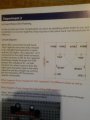
Now...I attached the schematic.I don't want you guys call me a lazy because I am asking your help.
I need someone to explain and if he can to draw me on a paper how does the current flow in every wire?What is it's value on every wire ?What is the voltage on every component ?What voltage is on each of the 2 capacitors and transistors ?Which components are in series and which are on parallel ?
I know a little about the series and parallel connections, but only on the simple schematics.Maybe I can't figure it, because of those capacitors and there connections with the tranzistors..
I am asking all this things because, this schematic(from what I understood), make that LED's to don't light both on the same time, only one each at a time.
I tried to simulate with Orcad, but I saw that on the transistor's base the voltage was 1 and a few, but the transistor's open voltage is 0.6V...
So I am asking you again, please, can you explain me all this things ? Maybe if I will see the flow of the current and voltage drawed on a paper, I will understand better.
Wait for your help,
Thank you very much!
I saw this video on youtube:
Now...I attached the schematic.I don't want you guys call me a lazy because I am asking your help.
I need someone to explain and if he can to draw me on a paper how does the current flow in every wire?What is it's value on every wire ?What is the voltage on every component ?What voltage is on each of the 2 capacitors and transistors ?Which components are in series and which are on parallel ?
I know a little about the series and parallel connections, but only on the simple schematics.Maybe I can't figure it, because of those capacitors and there connections with the tranzistors..
I am asking all this things because, this schematic(from what I understood), make that LED's to don't light both on the same time, only one each at a time.
I tried to simulate with Orcad, but I saw that on the transistor's base the voltage was 1 and a few, but the transistor's open voltage is 0.6V...
So I am asking you again, please, can you explain me all this things ? Maybe if I will see the flow of the current and voltage drawed on a paper, I will understand better.
Wait for your help,
Thank you very much!
Attachments
-
 2.1 MB Views: 42


