Facebook
 Google
 GitHub
 Linkedin
Hi
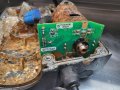
I have a pcb board which is covered in mud and rust.
I believe this could be a reason it is malfunctioning.
The pcb board mostly controls a servo motor.
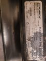
The pcb board a QR scan code.
Is it possible , once I clean it up from photos of the pcb , make a schematic so I can get a copy made from one of these Internet pcb board companies .
Regards
Som
I have a pcb board which is covered in mud and rust.
I believe this could be a reason it is malfunctioning.
The pcb board mostly controls a servo motor.
The pcb board a QR scan code.
Is it possible , once I clean it up from photos of the pcb , make a schematic so I can get a copy made from one of these Internet pcb board companies .
Regards
Som