Saturation at output for analog isolation

Thread Starter

chaitannya

Joined Apr 10, 2018
15
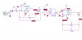
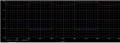
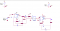
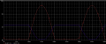
I am using HCNR200 for analog Isolation. I am using the schematic from the datasheet. Initially I observed is that the output goes into saturation, so I added feedback resistor R7. With this I am getting correct output, except a small glitch. There is slight saturation at the output, i.e. the output signal is not touching 0V. What can be the reason, how do I eliminate this.
If I use a rail to rail OpAmp, would this problem be eliminated ?

Regards,
Chaitannya
 

Attachments

AlbertHall

Joined Jun 4, 2014
12,622
You have an input which swings positive and negative of ground but you have only a positive supply for the opamps so their outputs cannot go negative.
 

danadak

Joined Mar 10, 2018
4,057
The uA741 is not even guaranteed to operate off single supply, 5V. Datasheet no
parameters stipulated at 5V, totally wrong part for this.

Definitely a RRIO part is in order.

Regards, Dana.
 

ebp

Joined Feb 8, 2018
2,332
Even nominally rail to rail amplifiers will not get the output all the way to the rail if there is any output current. They can typically get within a few tens of millivolts of the rail, which may not always be good enough. You also need to use amplifiers with very low input offset voltage. The µA741 was a pretty good amplifier for its time - 50 years ago. It just isn't worth using anymore.

I've used those couplers in a few industrial designs. With proper attention to detail the work very well at reasonable cost. There are analog isolation amplifiers that perform better, but the last time I looked, admittedly several years ago, they were a good deal more expensive.

The feedback must come entirely from the feedback detector in the optocoupler, with the exception of the frequency compensation capacitor, otherwise you completely defeat the intent of the circuit. The circuit relies on good ratiometric tracking between the feedback detector and the output detector.
 

Thread Starter

chaitannya

Joined Apr 10, 2018
15
Even nominally rail to rail amplifiers will not get the output all the way to the rail if there is any output current. They can typically get within a few tens of millivolts of the rail, which may not always be good enough. You also need to use amplifiers with very low input offset voltage. The µA741 was a pretty good amplifier for its time - 50 years ago. It just isn't worth using anymore.

I've used those couplers in a few industrial designs. With proper attention to detail the work very well at reasonable cost. There are analog isolation amplifiers that perform better, but the last time I looked, admittedly several years ago, they were a good deal more expensive.

The feedback must come entirely from the feedback detector in the optocoupler, with the exception of the frequency compensation capacitor, otherwise you completely defeat the intent of the circuit. The circuit relies on good ratiometric tracking between the feedback detector and the output detector.
Thanks for an elaborate explanation. I used 741 so that I can quickly get on with the simulation results. In the actual circuit I am planning to use OP777, this is RRIO with max 100uV offset voltage.
I have modified the circuit as you had suggested. The saturation issue was resolved by increasing value of R3. The output is quite acceptable now.
I hope I can go ahead with this schematic.
 

Attachments

AnalogKid

Joined Aug 1, 2013
12,076
Your output is half-wave rectified, which is an extreme form of distortion for an analog signal. Why is this acceptable?

ak
 

Thread Starter

chaitannya

Joined Apr 10, 2018
15
Your output is half-wave rectified, which is an extreme form of distortion for an analog signal. Why is this acceptable?

ak
It is unipolar. The input is supposed to be between 0-5V. I have used sine wave to analyse the response of the circiut. Sometime back I had tried this circuit on breadboard & I got saturated output, hence the sine wave. I think I should have used DC sweep to analyse the output.
 
Top