Filter LM4562 Output Saturation

Thread Starter

pdhaslam

Joined Dec 21, 2022
18
Hello folks

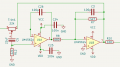
Hope you're all well. I'm flumoxed by my filter circuit. Designed a filter in LTSpice, based on something I got from the TI filter design program. The idea is to simulate a Celestion Creamback driver. LTSpice and KiCAD circuit:

Screenshot 2023-06-19 at 18.21.55.pngScreenshot 2023-06-19 at 18.32.05.png

Gives me the freq response:
Screenshot 2023-06-19 at 18.24.57.png

Here's the board with relevant components circled:
IMG_0512.jpg

Ignore C6 - didn't have a 4n7 cap so bodged it with two 10n in series. C8 seemed to do odd things so i removed it and it was better for it. C12 added for stability

LTSpice shows unity gain which makes sense and through the first op-amp is fine, the problem is the second half with the input fine but the output just flying the to rails fully saturated, whatever the input.

Tried different LM4562s and same response so assume the problem is my circuit?

Would be grateful for help!

Pat
 

Ian0

Joined Aug 7, 2020
13,104
Where did C8 come from? That looks like positive feedback!
And R45 should be outside the feedback loop.
A real Creamback has a big dip in the response at 1.5kHz due to a "bell mode" resonance. Perhaps you need a twin-T network in there to simulate that!
 
Last edited:

Thread Starter

pdhaslam

Joined Dec 21, 2022
18
thanks all, yes it was close enough to my eyes,

@Ian0 - yes, think my head started to hurt when thinking about getting the dip. C8 originally fixed an oscillation in a prototype (don't ask me why!) but seemed to lead to turning the input into a triangle wave

Have took some pictures of the oscilloscope. For a 1Vpp output from pin 1, I get 1 Vpp at pins 5 and 6 but this at pin 7:

IMG_0514.jpg

If I trimmed down the input so that Pin 1 was 73mVpp I managed to get this:

IMG_0516.jpg

if that helps at all!!
 

ericgibbs

Joined Jan 29, 2010
21,412
Hi Pat,
As you say, it shows the response in a different way, a method of showing the response of the circuit, with an actual frequency sweep.
E
 

Ian0

Joined Aug 7, 2020
13,104
It's part of the Sallen-Key low-pass filter.
Yes if it's there to stabilize the op amp for driving a capacitance load.
Aha! There's more than one C8 - the component numbers in the first diagram are different from those in the second.
I meant C8 in the Kicad screenshot, not C8 in the SPICE screenshot!
 

Ian0

Joined Aug 7, 2020
13,104
thanks all, yes it was close enough to my eyes,

@Ian0 - yes, think my head started to hurt when thinking about getting the dip. C8 originally fixed an oscillation in a prototype (don't ask me why!) but seemed to lead to turning the input into a triangle wave

Have took some pictures of the oscilloscope. For a 1Vpp output from pin 1, I get 1 Vpp at pins 5 and 6 but this at pin 7:

View attachment 296690

If I trimmed down the input so that Pin 1 was 73mVpp I managed to get this:

View attachment 296691

if that helps at all!!
See what happens if you get the resistor outside the feedback loop.
I suspect that the dip at 1.5kHz is sharper than it appears in the graph, as the graphs are always "smoothed", and I also suspect that the large changes in phase around the resonance will be important for the "tone".
This might be what you need
http://sim.okawa-denshi.jp/en/TwinTCRtool.php
 

Ian0

Joined Aug 7, 2020
13,104
I hope you didn't spend your hard-earned money on the LM4562 thinking it is a low-noise part.
It is, but only for low source impedances.
A 56k source impedance will increase the noise from 2.7nV/√Hz to 89.6nV/√Hz.
 

Thread Starter

pdhaslam

Joined Dec 21, 2022
18
WELL. I fixed it. It was super technical, I mean real quantum theory level stuff here.....

The clue was on here:

Screenshot 2023-06-19 at 18.32.05.png

look closer...

Screenshot 2023-06-19 at 18.32.05 2.png

AAARGGHHHHH!!!!! Used a wire to actually make the feedback netowkr part of the circuit...having banged my head against the wall for punishment....

Managed to look at the Freq Response in ARTA and overlaid the LTSpice sim, the brighter line is LT spice and the faded line is the ARTA screengrab:

Screenshot 2023-06-20 at 15.08.14.png

Will need to fiddle to get a steeper HF roll off, maybe add that notch filter in

Thanks for you time everyone

Pat
 

Attachments

Ian0

Joined Aug 7, 2020
13,104
Why do you like AM-radio or old telephone frequency response?
The top string of a guitar is 320Hz. There are 22 frets. The top fret would give two octaves above that 1280Hz. A bandwidth of 6kHz will include the 4th harmonic of the highest fret, or the 18th harmonics of the open string.
A typical guitar pickup of 6H driving 100pF of cable will roll off at 6.5kHz
 

Audioguru again

Joined Oct 21, 2019
6,826
Most humans hear sounds as high as 20kHz. Musical instruments have distinctive sounds due to their high harmonics.
Speech has consonants that reach 14kHz or higher for clarity.

Electric geetars with a poor high frequency response sound like a whistle or a buzzer. They probably muffle the highs to remove some of the awful distortion. Listeners are probably deafened from the loud playing anyway.
 

Thread Starter

pdhaslam

Joined Dec 21, 2022
18
Most humans hear sounds as high as 20kHz. Musical instruments have distinctive sounds due to their high harmonics.
Speech has consonants that reach 14kHz or higher for clarity.

Electric geetars with a poor high frequency response sound like a whistle or a buzzer. They probably muffle the highs to remove some of the awful distortion. Listeners are probably deafened from the loud playing anyway.
Hey

The reason is to mimic a guitar speaker, you can see earlier posts comaring the response of a creamback driver and my filter

Oddly once implemented the fre isn't the same with v poor bass, will have to do some fiddling!
 
Top