Ryobi 4v cordless drill

Thread Starter

spike1947

Joined Feb 4, 2016
537
D1 Is faulty. It looks like a normal 1 amp silicon diode. Any one of the 1N400x series should be OK. ( The x will be a digit between 1 and 7.) This digit is an indictor for the peak inverse voltage rating. Any one of the range should be OK for this application.

Les.
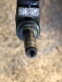
Have some N5397 Diodes , any good ?, on board now is IN5817, its ok have just ordered some 1N4004 .
 
Last edited:

LesJones

Joined Jan 8, 2017
4,511
The 1N5817 is a schottky diode which has a smaller forward voltage drop then a normal silicon diode. D1 is just for reverse polarity protection so I think any 1 amp rated diode will function in that position. Try using the N5397 (I think this is probably a 1N5397.) for now to see if you get about 6 volts at the the point where the battery positibe lead connects to the board.

Les.
 

Thread Starter

spike1947

Joined Feb 4, 2016
537
The 1N5817 is a schottky diode which has a smaller forward voltage drop then a normal silicon diode. D1 is just for reverse polarity protection so I think any 1 amp rated diode will function in that position. Try using the N5397 (I think this is probably a 1N5397.) for now to see if you get about 6 volts at the the point where the battery positibe lead connects to the board.

Les.
Tks will try that.
cheers
 

Paul_Sock

Joined Apr 24, 2024
9
It looks like there is no continuity of the etch on the negative supply between the charger input and the battey negative connection. I suspect that U1 and Q1 control the charging current. I can't find any data on U1 so I cant see a way to diagnose the problem further. You new picture of the area around U1 & Q1 is clear enough to see that there is no direct path between the negative charger input and the battery connection. The positive path is just via the PTC, and the 2 diodes. (R4 R5 and Q2 just drive the charge indicator LED.) From your previous voltage readings I was not clear to EXACTLY you connected your meter leads.
Set your meter to the DC volts range. With the battey NOT connected connect your negtive meter lead to the point on the board where the black charging wire is connected. Connect the positive lead from your meter to the point on the board where the red charging lead is connected and note the voltage reading. move the positive meter lead to the other side of the PTC and note the voltage reading. Move the positive meter lead to the point on the board where the red battery lead is connected and note the meter reading. If you have a resistor of about 100 ohms available connect it between the point where the black charger lead is connected to the board and the point where the red battery lead is connected to the board. Repeat the previous voltage tests again noting the readings. Thes test are to check the positive side of the path between the charger and the battery. So are you still waiting to change your ring doorbell sound? Connecting the 100 ohm resistor ts to put some load on the circuit in case the fault is not a total open circuit.

Les.
The missing negative path between charger and battery is confirmed. U1 and Q1 likely control charging current, but without a datasheet, further diagnosis is difficult. Perform the outlined voltage checks, including the 100 ohm resistor test. Examine U1 and Q1 for potential damage or abnormal heating.
 
Last edited:

Thread Starter

spike1947

Joined Feb 4, 2016
537
hi
Have fit a new D1 and a spare batt, was showing 3.95v, but still the same o change !
I just did a quick test from neg lead onto board and first pin on D1 and getting 7.7v then tested the other side of D1 , no voltage !, is that supposed to be, just fit a new diode to D1 !.

cheers
 

LesJones

Joined Jan 8, 2017
4,511
Are you sure that you are using the correct charger ? It is unusual for a diode to fail open circit AND have a new diode that is faulty. I can only think that you have a reversed polarity input and the diode is doing it's job of blocking the reversed polarity.

Les.
 

MrAl

Joined Jun 17, 2014
13,704
Hi
Sorry not been into electronics for quite awhile so a bit slow !.
Have a Ryobi 4v cordless drill, problem not charging, voltage at input 6.2v, voltage to battery 2.28v !, what do I have to check in between ?.

cheers
Spike
I bought a Ryobi drill from Home Depot years ago. It came with two battery packs which seemed like a good deal. They both died in a short time. I had to replace the NiCd batteries and redesign the charging circuit so it would not over charge the batteries. After 5 years with that, I switched to a lead acid battery with line cord connected to the drill body. That gave me a very long run time.

I do not buy Ryobi anything anymore. I've read they also fall short on the torque as compared to other manufacturers.

A 4v cordless drill is way old style. If you even got just an 18v drill now you'd see a big difference in torque. They also come with really fast chargers too now, you can charge in 1/2 hour or so.
 

Thread Starter

spike1947

Joined Feb 4, 2016
537
The missing negative path between charger and battery is confirmed. U1 and Q1 likely control charging current, but without a datasheet, further diagnosis is difficult. Perform the outlined voltage checks, including the 100 ohm resistor test. Examine U1 and Q1 for potential damage or abnormal heating.
Are you sure that you are using the correct charger ? It is unusual for a diode to fail open circit AND have a new diode that is faulty. I can only think that you have a reversed polarity input and the diode is doing it's job of blocking the reversed polarity.

Les.
Hi
Tks for that, will check again the charger output etc.
 

Thread Starter

spike1947

Joined Feb 4, 2016
537
I bought a Ryobi drill from Home Depot years ago. It came with two battery packs which seemed like a good deal. They both died in a short time. I had to replace the NiCd batteries and redesign the charging circuit so it would not over charge the batteries. After 5 years with that, I switched to a lead acid battery with line cord connected to the drill body. That gave me a very long run time.

I do not buy Ryobi anything anymore. I've read they also fall short on the torque as compared to other manufacturers.

A 4v cordless drill is way old style. If you even got just an 18v drill now you'd see a big difference in torque. They also come with really fast chargers too now, you can charge in 1/2 hour or so.
Hi
Tks for your reply, sorry a bit mis leading it is a cordless screwdiver.
cheers
 

MrAl

Joined Jun 17, 2014
13,704
Hi
Tks for your reply, sorry a bit mis leading it is a cordless screwdiver.
cheers
Oh ha ha, ok, so it's probably one of those small ones. They do look handy though.
The 18v and up models are really strong though, lots of torque, no problem putting a screw into a wood stud.

Long time ago I had a small electric screwdriver. Used two NiCd cells. Wasn't too bad I guess as it was geared way down. I made a chuck for it so I could use it as a drill too, but it was pretty slow. The 18v models go much faster with lots of torque too.
 

Thread Starter

spike1947

Joined Feb 4, 2016
537
Are you sure that you are using the correct charger ? It is unusual for a diode to fail open circit AND have a new diode that is faulty. I can only think that you have a reversed polarity input and the diode is doing it's job of blocking the reversed polarity.

Les.
Hi Less
You are correct, there was a polarity problem, checked polarity on the transformer outlet plug and that is showing + Positive for the centre pin on the plug and - Negative on the outer casing of the plug, but when I checked the conection to the board it is opposite, how is that possible for the socket on the pcb to change the polarity ?.
cut socket off and wired direct to board and whallah now charging phew.
I am still baffled has to how that can possibly happen.

Thanks again for you help and time.

cheers
Spike
 

LesJones

Joined Jan 8, 2017
4,511
I assume it must have worked originally so either someone has soldered the wires onto the power connector the the wrong way round or you are not using the original power supply. Did you not notice that the meter was showing negative readings ?

Les.
 

Thread Starter

spike1947

Joined Feb 4, 2016
537
I assume it must have worked originally so either someone has soldered the wires onto the power connector the the wrong way round or you are not using the original power supply. Did you not notice that the meter was showing negative readings ?

Les.
Hi
Nothing has been done to it , apart from cleaning the plug and socket, was a bit dirty , I use it it quite often, when it first stopped charging !.
So no not touched, it just stopped charging one time .
cheers
 

Thread Starter

spike1947

Joined Feb 4, 2016
537
Hi
Nothing has been done to it , apart from cleaning the plug and socket, was a bit dirty , I use it it quite often, when it first stopped charging !.
So no not touched, it just stopped charging one time .
cheers
Hi
It must be something in the socket that had broken or something, no I didnt check the polarity no reason to, it just didn't charge when I plugged it in, I use it at least a couple of times a week, so had a lot of use, it is very weird, should of taken pics to show you, will wire plug back on to see if it is still showing the same results .

cheers
Spike
 

LesJones

Joined Jan 8, 2017
4,511
When you were doing the requested voltage tests did you not think it was very odd for the meter to display negative readings ?
I am assuming that the power connector is the coaxial type. If so I can't see thatany break in the socket would reverse the polarity.
Most devices and plug in power supplies have pictures of the connectors showing if the center pin is + or -. Can you post pictures of these markings.
Les.
 

Thread Starter

spike1947

Joined Feb 4, 2016
537
When you were doing the requested voltage tests did you not think it was very odd for the meter to display negative readings ?
I am assuming that the power connector is the coaxial type. If so I can't see thatany break in the socket would reverse the polarity.
Most devices and plug in power supplies have pictures of the connectors showing if the center pin is + or -. Can you post pictures of these markings.
Les.
Hi
Ime not sure I noticed it tbh, transformer lead is just a twin wire, there is no markings on the plug, have ordered a new socket, nothing has been touched and has been charging fine, it gets charged prob once every couple of weeks, I use it regulary for small electrical items repair that I collect locally then they go to a local charity shop if ok ( I do PAT test) items after repair.
cheers
Spike
 

Attachments

Top