Facebook
 Google
 GitHub
 Linkedin
Hi
Sorry not been into electronics for quite awhile so a bit slow !.
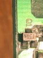
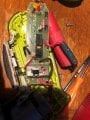
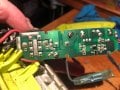
Have a Ryobi 4v cordless drill, problem not charging, voltage at input 6.2v, voltage to battery 2.28v !, what do I have to check in between ?.
cheers
Spike
Sorry not been into electronics for quite awhile so a bit slow !.
Have a Ryobi 4v cordless drill, problem not charging, voltage at input 6.2v, voltage to battery 2.28v !, what do I have to check in between ?.
cheers
Spike
Attachments
-
 2.2 MB Views: 7
 -
 2.2 MB Views: 7