 Facebook
 Google
 GitHub
 Linkedin
Greetings all,
This is my first post, so please forgive me if this isn't posted in the right location or additional information is necessary.
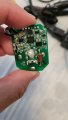
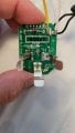
I am trying to modify a Ryobi P119 charger, as it is worthless in its factory form. I would like to increase it's charging power from the stock 6.5w to 20+ watts. The PCB and traces appear sufficient, but I am not sure which resistor sets the amperage. Connecting a 30w 20v DC power supply results in approximately 12w output.
Attached are photos of the PCB in question. Thank you in advance for any assistance.
This is my first post, so please forgive me if this isn't posted in the right location or additional information is necessary.
I am trying to modify a Ryobi P119 charger, as it is worthless in its factory form. I would like to increase it's charging power from the stock 6.5w to 20+ watts. The PCB and traces appear sufficient, but I am not sure which resistor sets the amperage. Connecting a 30w 20v DC power supply results in approximately 12w output.
Attached are photos of the PCB in question. Thank you in advance for any assistance.
Attachments
-
 1,020.3 KB Views: 4
 -
 1.2 MB Views: 3


