 Facebook
 Google
 GitHub
 Linkedin
I been watching EEV's video on Cockcroft Voltage Multiplier again.
It's a great vid and among other things he makes clear upper side is pulsating voltage and bottom side is steady dc. He explains why in the beginning of the vid.
And then i stumbled on this russian craziness.
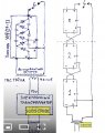
So they used this 3 stage multipliers from old TVs. You can see in the diagram is missing first top capacitor, but i guess that's a mistake.
What i find strange is how they connected them.
To stack them they drilled a hole marked A in diagram, which is presumably the top part of the last stage, and they connected it to "ground" of the next multiplier.
They also connected bottom side of the last stage marked + to top side of next multiplier.
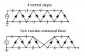
I made a diagram to compare normal 4 stages to how they connected them. I used 2 and 2 instead of 3 and 3 but same thing.
I find it strange and it sure does not look like the same circuit like normal 4 stages.
It obviously works, but why does it work connected like this?
Anyone?
It's a great vid and among other things he makes clear upper side is pulsating voltage and bottom side is steady dc. He explains why in the beginning of the vid.
And then i stumbled on this russian craziness.
So they used this 3 stage multipliers from old TVs. You can see in the diagram is missing first top capacitor, but i guess that's a mistake.
What i find strange is how they connected them.
To stack them they drilled a hole marked A in diagram, which is presumably the top part of the last stage, and they connected it to "ground" of the next multiplier.
They also connected bottom side of the last stage marked + to top side of next multiplier.
I made a diagram to compare normal 4 stages to how they connected them. I used 2 and 2 instead of 3 and 3 but same thing.
I find it strange and it sure does not look like the same circuit like normal 4 stages.
It obviously works, but why does it work connected like this?
Anyone?
Attachments
-
 113.3 KB Views: 32
 -
 48.5 KB Views: 33


