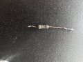
Hello, i've just been to RS Components (Leeds) to see if they had a part i require, i showed them it but they didn't know what it was, has anyone got an idea of what it is?
Not for sure, but it looks like it might be a low val. resistor?
Thermal fuse?
What function was it performing and what circuit/device?
What does it measure?
Max.
Hi, thanks for your replies, the said item came from a power board of a vinyl cutter, if i post a pic of the board and where it was on the board, would this be of help to anyone?
If you had a tummy-ache would you cut yourself open or go to a known quack to cut you open. No!
Proper electronics repair requires knowledge and experience, and sometimes the right information and test equipment.
A resistor does not blow on its own. If a component went bad there are usually underlying reasons why it failed. One has to fix the cause of those failures before replacing a blown component.
To repair a complex piece of electronics one needs a lot more information such as the make and model of the unit, the history and past performance of the unit, a knowledge on the electronic design of the unit, and most importantly, a circuit schematic.
If the power supply is not working, your chance of repairing it is very low. Your next bet would be to replace the power supply as a complete module. You may need to investigate why the power supply failed in the first place.
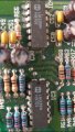
I agree with others. It looks like an film type resistor that has burned all its "paint" off. Judging by the number of "turns" in the spiral of the film, it is probably quite low in value, but what that value might be is impossible to say. I have seen somewhat less burned resistors that were still pretty close to their original value, so it is worth trying to measure it.
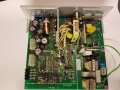
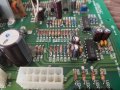
OK, looking at the photo of the board:
That is a switch mode power supply. Because I think the resistor is low resistance, my first guess is that it was for current sensing and between circuit common and the source (if a MOSFET) or emitter (if a bipolar transistor, BJT) of the switch. If that is what it is, then it is highly likely that the FET or BJT has failed short-circuit. There is some chance it might just have run too hot because the location impairs cooling. Usually if the FET or BJT shorts, it just blows a piece out of the film of a current sense resistor, leaving it looking pretty normal except for a small black spot.
There are two other places in that sort of circuit where low value resistors are common. One is in the part that supplies the power to keep the circuit running from a winding on the transformer. The other is in series with the gate of a FET if that is what is used as a switch. Neither would burn up without a destructive failure in another part. Overheating and short-circuit failure of the FET or BJT is not uncommon.
The switch (FET or BJT, the former is most common these days) is the device in the yellow circle that is mounted on the heatsink. Provided the board has been disconnected from mains for some time, you can measure the resistances among its pins. If you were to view it looking at its face with the pins downward, the most likely short circuit is between the centre ("drain") and right-hand ("source") pin. If the dead resistor was between the source pin and the negative side of one of those big black capacitors it would confirm my suspicion of it being for current sense.
Every bit of that circuitry should be considered to be connected directly to AC mains "hot" for safety purposes. It is something I would not encourage an inexperienced person to try to fix.
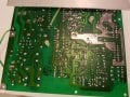
Having said that, an additional photo of the back of the board showing where the dead part was and some of the surrounding area might be helpful.
Thanks for all replies, i did try and get it repaired by an online specialist but they told me they only deal with Trade and required me to be VAT registered :-(
The power supply works sometimes, then when i turn it off and try turn it back on again straight after, nothing, but if i try the day after it normally powers on?
Thanks again people, looks like my Vinyl cutter is for the scrap heap :-(
Yes, when it was in it does work sometimes and would work perfectly until i switch it off, then it takes a while, maybe next day until i can get it to turn back on.
When you say you have to wait for it to turn back on, are you basing this on being fully operational or some sign that the power supply is coming up?
It would be very odd for the power supply to take more than a few tens of minutes, at most, to turn on again for any fault I can think of. However, if the power supply comes up to operating voltage more slowly than usual or something like that, the microprocessor that runs the cutter might not initialize (reset) properly, even though the power supply voltages all come up and are OK. What may be going on is that minor changes in AC line voltage have some influence and it then is kind of a "random" thing whether the cutter comes up.
I would suggest the next step is to try to measure some of the DC voltages from the output of the power supply. If you work carefully and stay away from the "primary" side of the supply that is connected to the AC mains, this can be done safely.
It may be that the burned part is indeed adequately functional, and just looks like it is the problem when actually something else is at fault. If the cutter has been used a lot, there is a possibility that capacitors in the power supply have "worn out." This is a very common thing. Repair can be a bit time consuming, but the parts usually aren't too expensive.
Again, some more photos of the board would be helpful. They would probably allow us to figure out where the outputs of the power supply are and where you need to measure voltages. Photos of both the top of the board showing components and the bottom showing connections would be good to have.
If this is a commercial vinyl cutter (as opposed to a small "consumer" type) it is probably quite expensive to replace, so it seems worthwhile to try to repair it. It looks like the dangerous part of the supply may well be generally OK, which is a very big plus.
That's a very complex power supply board! It looks like there is a whole bunch of circuitry that "supervises" the supply to assure that all of the voltages are within acceptable limits.
I think that it is probably a "2-switch forward converter" - not that that really matters much at the moment.
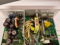
Can you add some photos that show any detail of what is mounted on the heatsink plate adjacent to the transformer (might not be possible to see markings - it looks like there may be a mounting clip that covers the front of the part) and also the small vertical circuit board nearby. If you can't see the markings on the part on the heatsink plate, can you see a reference designator (e.g. Dxxx or Qxxx or the like) near it? It would be helpful to know what is marked on the part on the small heatsink in the corner of the small vertical circuit board.
The small vertical board is probably the main control circuit for the switcher, but a device on a heatsink on it is something of an oddity. The control circuit itself needs power. Very often the power first comes from the main DC input (the big caps you have removed) via a resistor or something a bit more complex, then once the supply is up and running it comes from an extra winding on the transformer. If things don't go right at startup, the supply will try to start but can't keep going for more than a small fraction of a second. Sometimes a resistor is used in series with the winding mentioned to limit peak current (in other outputs inductors do a more "proper" job, but an inductor isn't usually worth it for the low average current for this winding). It may be that that is what the burned resistor is for. If I can get a better idea of what is there I can possibly improve my guesses about what is doing what.
Look over all of the electrolytic capacitors to see if any of them show signs of the tops bulging. They look OK in the photos, but minor bulging can be hard to see but still a sign the cap is bad.
What is marked on IC2? (the one to the left of the DANGER marking)
Sorry, I missed your latest when it was first posted.
Now I'm baffled! The TL494, IC2, is the main switcher control chip, but it is "resident" on the low-voltage side. This is nothing too unusual, except that it means that there must be some source of power for it and its associated circuitry that comes from somewhere other than the circuit it controls. It can't be started in the way I mentioned previously because of the need for electrical isolation between the high voltage and low voltage sides. This normally means there will be a "housekeeping" power supply. Sometimes it is a small switcher on the main board, sometimes a separate small supply.
Is there some other small power supply in the cutter? Something with a small iron-core transformer?
I also mislead you as to what I needed more photos of. I need to see what is on the aluminium plate that is near the main transformer (the one with the yellow tape and all the wires sprouting out of the top) and the small vertically-mounted "daughter board" that is near it - the one with the green disc capacitor on it. Previously I thought the small board was the main control, but now I think it may have something to do with automatic line voltage selection.
 Facebook
 Google
 GitHub
 Linkedin
 402.6 KB Views: 58
") just don't do the parts anymore for it.
just don't do the parts anymore for it.