RLC circuit paralel with transmissor

Thread Starter

pijolysss

Joined Nov 30, 2017
17
Hello everybody!

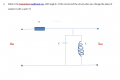
I have a problem with that exercise(check picture).
I think I resolved the first part of the statement good, but what happen when you change the place of resistor R with L and C?
The solution that I have for the first part is the next one(I think its correct):
Z1=R
Z2=jωL/(1-ω^2 LC)
Ku=(jω L/R (1-ω^2 LC)+(ω L/R)^2)/((1-ω^2 LC)^2+(ω L/R)^2 )
Then... |Ku |=(ωL/R)/√((1-ω^2 LC)^2+(ω L/R)^2)
And for shift Angle:
Ф(ω)=arctan⁡(R/Lω(1-ω^2 LC))
So, my doubt is what happen when you change the place of resistor R with L and C? Is the same solution than before?

Thanks to all! :)
 

Attachments

MrAl

Joined Jun 17, 2014
13,728
Hello everybody!

I have a problem with that exercise(check picture).
I think I resolved the first part of the statement good, but what happen when you change the place of resistor R with L and C?
The solution that I have for the first part is the next one(I think its correct):
Z1=R
Z2=jωL/(1-ω^2 LC)
Ku=(jω L/R (1-ω^2 LC)+(ω L/R)^2)/((1-ω^2 LC)^2+(ω L/R)^2 )
Then... |Ku |=(ωL/R)/√((1-ω^2 LC)^2+(ω L/R)^2)
And for shift Angle:
Ф(ω)=arctan⁡(R/Lω(1-ω^2 LC))
So, my doubt is what happen when you change the place of resistor R with L and C? Is the same solution than before?

Thanks to all! :)

Hi,

Without giving the entire result, if you have a transfer function Hs=H(s) for the output the output is then:
Vout=Vin*Hs

and since you now know the output voltage Vout you can then immediately calculate the voltage across the resistor:
Vr=Vin-Vout

and since Vout is defined above we get:
Vr=Vin-Vin*Hs

or:
Vr=Vin*(1-Hs)

and if you switch LC and R in the circuit you will be looking at the voltage across the resistor Vr as the output so that would be the solution. You then just have to recalculate the actual amplitude and phase shift. You may even find more simplifications.

Another approach is to transform the transfer function into a function of impedances:
(zC*zL)/(zC*zL+R*zL+R*zC)

and now you can swap any two components and that gives you the new transfer function.

You can even swap sets of impedances but you have to factor into the sets you need to swap.

As an example of swapping C and R, just replace all zC with Rx and replace all R with zC, then replace Rx with R and you have the new transfer function after replacing the impedances with the individual impedances for the respective elements.

To swap LC with R you would have to first factor into a form which has both L and C impedances in parallel.

To get to the impedance form of the transfer function, factor into sets of s*L and 1/(s*C) or if you prefer into j*w*L and 1/(j*w*C). You must be able to do this for this method to work because every impedance of a given element must be replaced with the new impedance for both elements being swapped.

This works on so many networks it is definitely worth mentioning, and may even work on every network but i cant prove that right now.
 
Last edited:

MrAl

Joined Jun 17, 2014
13,728
Thank you very much!
Hi,

You're welcome :)

I especially like the impedance swapping method. I discovered this property myself a long time ago before the internet became popular so i am not sure what general area of study this would fall under. Perhaps topology or graph theory, but dont quote me on that :)
I guess we can call it, "Topological circuit transformation by impedance interchange", or something. I use the word "interchange" rather than "swapping" because it is possible to change impedances outright too and thus vary the topology that way as well.

Good luck in your studies.
 
Top