Rf amplifier output

Thread Starter

Hellerx44

Joined Apr 6, 2021
52
Hi
Sorry for the silly question but,
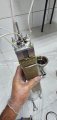
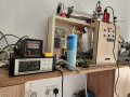
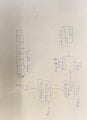
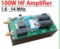
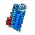
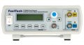
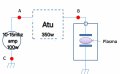
I need some help for a project, I'm building rf plasma generator using function generator with preamplifier => 100w rf amplifier 1.8to54mhz. This going to automatic antenna tuner. The question is how to get the high voltage output to the plasma chamber dose it needs aircore transformer after the atu?, it should be around 3 to 4 kv? Something I'm missing in the attached picture?
Thanks
 

Attachments

nsaspook

Joined Aug 27, 2009
16,259
Normally for a plasma chamber the RF match is bolted directly on the chamber with a HV feed-through to the processing plasma chamber internal field plates. You might also need a plasma igniter circuit to strike the plasma to get it started at such low power levels.
https://www.semigroup.com/rf-match-tuning/


Induction plasma

Know the dangers of this type of project. RF can be dangerous and RF burns are nasty.
 
Last edited:

Thread Starter

Hellerx44

Joined Apr 6, 2021
52
Normally for a plasma chamber the RF match is bolted directly on the chamber with a HV feed-through to the processing plasma chamber internal field plates. You might also need a plasma igniter circuit to strike the plasma to get it started at such low power levels.
https://www.semigroup.com/rf-match-tuning/


Induction plasma

Know the dangers of this type of project. RF can be dangerous and RF burns are nasty.
Thanks for the reply,
Can you tell me what is output voltage from automatic antenna tuner attached to 100w amplifier let's us say 15mhz?
 

MisterBill2

Joined Jan 23, 2018
27,251
It is not likely that an "antenna tuner" will be able to match the RF output to the plasma generator, considering that plasma is generally a quite good conductor. The destruction of the automatic tuner would be rather discouraging.
 

nsaspook

Joined Aug 27, 2009
16,259
Thanks for the reply,
Can you tell me what is output voltage from automatic antenna tuner attached to 100w amplifier let's us say 15mhz?
Why 15MHz? The ISM frequency normally used is 13.56MHz. The output voltage depends on the plasma breakdown voltage that can vary from several factors like gas density in the vacuum, the size of the changer and electrode spacing.
https://www.analog.com/en/resources/interactive-design-tools/rf-impedance-matching-calculator.html

You know the values of the plasma parameters, like the capacitance and the conductance of the discharge and the variation of these with the operating conditions of the system, i.e. the pressure, the frequency and the input power, put all of that into a EM solver modeler like COSMOL. https://www.comsol.com/

Before breakdown voltage the output voltage can be very high (several hundred or thousands at higher power) as the match is trying to tune a high impedance load. After breakdown the impedance drops to the value of the complex plasma load value so the operating voltage are normally lower.
 
Last edited:

Thread Starter

Hellerx44

Joined Apr 6, 2021
52
Why 15MHz? The ISM frequency normally used is 13.56MHz. The output voltage depends on the plasma breakdown voltage that can vary from several factors like gas density in the vacuum and electrode spacing. Before breakdown voltage the output voltage can be very high (several hundred or thousands at high power) as the match is trying to tune a high impedance load. After breakdown the impedance drops to the value of the complex plasma load value.
I have no issues with the frequency, let be 13.56MHZ, my question was about the high voltage output, how to get the high voltage? Is there a transformer? Check this guy
https://mullinscyclotron.weebly.com/hv-rf-system.html
 

nsaspook

Joined Aug 27, 2009
16,259
I have no issues with the frequency, let be 13.56MHZ, my question was about the high voltage output, how to get the high voltage? Is there a transformer? Check this guy
https://mullinscyclotron.weebly.com/hv-rf-system.html
Those types of questions seem to imply you don't understand the fundamentals of what's needed.
Your link is to a guy building a cyclotron, not a RF plasma generator. The RF system in that link is for acceleration plates.
1726860700851.png
http://hyperphysics.phy-astr.gsu.edu/hbase/magnetic/cyclot.html
 

Thread Starter

Hellerx44

Joined Apr 6, 2021
52
Those types of questions seem to imply you don't understand the fundamentals of what's needed.
Your link is to a guy building a cyclotron, not a RF plasma generator. The RF system in that link is for acceleration plates.
View attachment 332111
http://hyperphysics.phy-astr.gsu.edu/hbase/magnetic/cyclot.html
I know what cyclotron is. My project is kind of particals accelerator. Check my ion source with plasma. https://youtube.com/shorts/EwO9JUzvH7s?si=LIqlXN48Uhi67TEh
 

nsaspook

Joined Aug 27, 2009
16,259
I know what cyclotron is. My project is kind of particals accelerator. Check my ion source with plasma. https://youtube.com/shorts/EwO9JUzvH7s?si=LIqlXN48Uhi67TEh
What exactly is your "kind of particle accelerator" project? There is a "plasma" source in the cyclotron link but it's a simple electron heater (with a filament) used to strip the source particle gas into ions to be accelerated by the RF plates from the matching system.
 

Thread Starter

Hellerx44

Joined Apr 6, 2021
52
What exactly is your "kind of particle accelerator" project? There is a "plasma" source in the cyclotron link but it's a simple electron heater (with a filament) used to strip the source particle gas into ions to be accelerated by the RF plates from the matching system.
Well. There is different types of ion sources, I'm using PIG ion source. Google it.
Now, I finished the project only the rf system still working on it, this partials accelerator is linear accelerator it's compact and low energy with drift tubes and magnetic system.
 

Attachments

nsaspook

Joined Aug 27, 2009
16,259
Well. There is different types of ion sources, I'm using PIG ion source. Google it.
Now, I finished the project only the rf system still working on it, this partials accelerator is linear accelerator it's compact and low energy with drift tubes and magnetic system.
I don't need to google it, I've seen it before. it's pretty neat but I agree with most of what was said there.
https://www.physicsforums.com/threads/pig-penning-ionization-gauge-ion-source.1063547/
 
Last edited:

Thread Starter

Hellerx44

Joined Apr 6, 2021
52
I don't need to google it, I've it before. it's pretty neat but I agree with most of what was said there.
https://www.physicsforums.com/threads/pig-penning-ionization-gauge-ion-source.1063547/
I don't need to google it, I've it before. it's pretty neat but I agree with most of what was said there.
https://www.physicsforums.com/threads/pig-penning-ionization-gauge-ion-source.1063547/
I went low in the frequency.
So do you have the solution for my question?
 

Thread Starter

Hellerx44

Joined Apr 6, 2021
52
Sure. I'd like to see a full electrical schematic diagram of your project as I'm not sure what the actual function of the RF system is.
As in the picture attached , the question mark is my problem, as the guy with cyclotron emo box transformer or there is another way to get the high voltage ?
 

Attachments

nsaspook

Joined Aug 27, 2009
16,259
Exactly what type of drift tube type are you using? The quick answer is yes, a setup transformer will work in his case because of the need of balanced and opposite polarity acceleration fields in the cyclotron.
 

Thread Starter

Hellerx44

Joined Apr 6, 2021
52
Exactly what type of drift tube type are you using? The quick answer is yes, a setup transformer will work in his case because of the need of balanced and opposite polarity acceleration fields in the cyclotron.
Ok thanks. For the quick answer, but I still need more information if there is a calculator fro the transformer winding.
Regarding the drift tube I designed it and cnc done on china. It has place for magnets (SmCo) . It seems we are exchanging information slowly. Give me some help and I will send you more information privately .
 

Attachments

nsaspook

Joined Aug 27, 2009
16,259
Ok thanks. For the quick answer, but I still need more information if there is a calculator fro the transformer winding.
Regarding the drift tube I designed it and cnc done on china. It has place for magnets (SmCo) . It seems we are exchanging information slowly. Give me some help and I will send you more information privately .
No thanks, it's your project.
 
Top