Reverse polarity DC motor cyclic timer

crutschow

Joined Mar 14, 2008
34,933
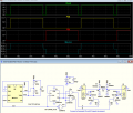
Below is the LTspice sim of a 555 circuit with two relays forming a bridge, that reverses the motor with off-time between reversals.
The motor (blue trace) has an off-time between reversals equal to the low period of the 555 (determined by the value of R2).

Edit: Changed output gates from AND to NOR to eliminate output glitches from a race condition.
1714670063019.png
 
Last edited:

MisterBill2

Joined Jan 23, 2018
19,638
Below is the LTspice sim of a 555 circuit with two relays forming a bridge, that reverses the motor with off-time between reversals.
The motor (blue trace) has an off-time between reversals equal to the low period of the 555 (determined by the value of R2).

(Note the glitches shown in the logic outputs are due to propagation delays, but they are too short to affect relay operation.)

View attachment 321380
I recognize that relay circuit! Simple and easy and built in dynamic braking.
 

Thread Starter

dhruvpatel00764

Joined Apr 28, 2024
20
I have not provided any Circuit suggestions yet,
because I needed more information about the equipment that will actually be used in the project.

Selecting a Gear-Motor that would be appropriate for your project could take many hours of research,
and, I don't know which suppliers are available to your location.

A much less powerful Motor, with gear-Reduction added,
will do the work that You are asking for.
( it looks like this is a Butter-Churn project )

Since You are wanting to reduce the physical-size of the Butter-Churn,
much less Power is required from the Motor, compared to the Churn that is in the video.

The RPM of the Churn must be kept very low to prevent splashing-out all of the Milk.

The Gear-Reduction will provide the additional Torque required
for when the mixture starts to get very thick and viscous.

You can't have too much Torque,
but You CAN DEFINITELY have too much RPM,

this is the reason for having the Gear-Reduction on the Motor.

This project is a lot of work, for a device that seems to have very limited increased-value
over the commercially available options.

If You want to go to the trouble to find, and purchase, an appropriate ~1000-RPM Gear-Motor,
I will provide You with a very versatile Automatic-Motor-Reversing, and Speed-Controlling-Circuit.

I will be waiting to see the selection of Gear-Motors that
You find that may be appropriate for this application.
Some will certainly be better suited to the job than others.
.
.
.
thank you for this all explaination may be we will use this motor

https://www.amazon.in/Robodo-Electronics-REL_43-Geared-Robotics/dp/B00MYG7GHI

or may be this

https://robokits.co.in/motors/dc-mo...otor-high-torque-dc-geared-12v-300rpm-grade-a

all these motors available in 200-300-500 rpm. can you please suggest wich motor we will use for this project?
 

Thread Starter

dhruvpatel00764

Joined Apr 28, 2024
20
Below is the LTspice sim of a 555 circuit with two relays forming a bridge, that reverses the motor with off-time between reversals.
The motor (blue trace) has an off-time between reversals equal to the low period of the 555 (determined by the value of R2).

Edit: Changed output gates from AND to NOR to eliminate output glitches from a race condition.

View attachment 321424
thank you for this diagram and your time. can you please draw a circuit so i can make wiring diagram of this? because i don't know how to connect these CD4001B, CD4013B etc.i want to make these circuit because all these components used in this circuit available here. and also what will be power supply rating i use?

@LowQCab any input from you regarding this circuit?
 

LowQCab

Joined Nov 6, 2012
4,362
This Gear-Motor would be my pick between the 2 choices that You provided,
it will do the job with plenty of reserve Power.

300 RPM is probably a good Maximum-Output-Speed for your project,
but,
there is no need to make the Motor "Scream" at ~18,000-RPM all the time,
so a Gear-Motor with a higher Output-RPM-rating would be better,
with the Motor running much slower than it's maximum RPM,

( 500-RPM-?, the web-page is not very clear about different models with different RPM-Gearing ).

With a higher-rated Output-RPM, ( caused by a different Internal-Gear-Ratio )
the Motor will be running at a more "comfortable", and less irritating, RPM,
of possibly ~10,000-RPM, or even less.
6,000-Motor-RPM would probably be even better,
if the Output-RPM could remain at, or near, ~300-RPM.

This would mean that the Motor would be running at
approximately ~1/3 of it's maximum-rated-Motor-RPM,
this would require a Gear-Motor capable of ~1,000-RPM maximum Output-RPM.

1/3 of ~1,000 = ~333 Output-RPM.
1/3 of ~18,000 = ~6,000 Motor-RPM

I will start working on my recommended Circuit,
it may take a few days, depending on finding enough spare time.
.
.
.
 

Thread Starter

dhruvpatel00764

Joined Apr 28, 2024
20
This Gear-Motor would be my pick between the 2 choices that You provided,
it will do the job with plenty of reserve Power.

300 RPM is probably a good Maximum-Output-Speed for your project,
but,
there is no need to make the Motor "Scream" at ~18,000-RPM all the time,
so a Gear-Motor with a higher Output-RPM-rating would be better,
with the Motor running much slower than it's maximum RPM,

( 500-RPM-?, the web-page is not very clear about different models with different RPM-Gearing ).

With a higher-rated Output-RPM, ( caused by a different Internal-Gear-Ratio )
the Motor will be running at a more "comfortable", and less irritating, RPM,
of possibly ~10,000-RPM, or even less.
6,000-Motor-RPM would probably be even better,
if the Output-RPM could remain at, or near, ~300-RPM.

This would mean that the Motor would be running at
approximately ~1/3 of it's maximum-rated-Motor-RPM,
this would require a Gear-Motor capable of ~1,000-RPM maximum Output-RPM.

1/3 of ~1,000 = ~333 Output-RPM.
1/3 of ~18,000 = ~6,000 Motor-RPM

I will start working on my recommended Circuit,
it may take a few days, depending on finding enough spare time.
.
.
.
i will find near 6000rpm motor outputs 300rpm with gear, i will waiting for your circuit because this is my first project so I'm very excited. thank you for your time and knowledge. please take your time with circuit.
 

crutschow

Joined Mar 14, 2008
34,933
draw a circuit so i can make wiring diagram of this
I will let you do that.
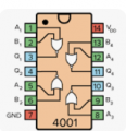
Below are the pinouts for the IC's which you can use to make the wiring diagram.
  • S and R on the flip-flop pinout are PRE and CLR on the schematic.
  • There are two flip-flops in the 4013 package, you will use only one. There is also one unused 4001 gate.
  • You can use either flip-flop and any of the three gates for the circuit.
  • The circuit power (Vcc, +Ve, and Vdd) will be the voltage you use to power the motor.
  • Make sure and connect all unused inputs (not outputs) on the 4001 and 4013 to ground, or the IC may overheat.
1714655032356.png1714655112581.png

1714655487550.png
 

Thread Starter

dhruvpatel00764

Joined Apr 28, 2024
20
I will let you do that.
Below are the pinouts for the IC's which you can use to make the wiring diagram.
  • S and R on the flip-flop pinout are PRE and CLR on the schematic.
  • There are two flip-flops in the 4013 package, you will use only one. There is also one unused 4001 gate.
  • You can use either flip-flop and any of the three gates for the circuit.
  • The circuit power (Vcc, +Ve, and Vdd) will be the voltage you use to power the motor.
  • Make sure and connect all unused inputs (not outputs) on the 4001 and 4013 to ground, or the IC may overheat.
View attachment 321451View attachment 321452

View attachment 321454
thanks @crutschow for your input but I'm from computer background i don't understand how this works all connected together, so i request you can you please make a complete circuit with pinout so i can construct a pcb with help of my friend, thanks in advance.
 

crutschow

Joined Mar 14, 2008
34,933
t I'm from computer background i don't understand how this works all connected together, so i request you can you please make a complete circuit with pinout
Well, then now is the time to learn how to go from a schematic to wiring diagram.
Just put the part pin numbers on my schematic from the IC pinouts I posted.
Note that all the ground symbols and Vcc symbols are connected, as it makes a cleaner schematic to use the symbols rather than show the wires.
That is then how you wire all the parts together.
If you have questions about doing that, post on this thread.

Sorry, but I don't feel it necessary to spoon feed you the wiring diagram.
If you want to dabble in electronics you need to understand how to work from a schematic.
 
Last edited:

Thread Starter

dhruvpatel00764

Joined Apr 28, 2024
20
Well, then now is the time to learn how to go from a schematic to wiring diagram.
Just put the part pin numbers on my schematic from the IC pinouts I posted.
Note that all the ground symbols and Vcc symbols are connected, as it makes a cleaner schematic to use the symbols rather than show the wires.
That is then how you wire all the parts together.
If you have questions about doing that, post on this thread.

Sorry, but I don't feel it necessary to spoon feed you the wiring diagram.
If you want to dabble in electronics you need to understand how to work from a schematic.
thanks for advice, as it's completely different field, but i will try as @MaxHeadRoom suggested using kicad 8 software. i will create circuit and post it here.
 

LowQCab

Joined Nov 6, 2012
4,362
Well,
if your looking for slick behavior, with lots of adjustability, this is it,
but it costs twice as much as I estimated, probably around ~60 to 70 USD after shipping etc.

It has a Cycle-Rate-Knob, and a Maximum-Speed-Knob with the Power-Switch built-in to it.
The Cycle-Rate is from 3 Cycles per Second, to 3-Seconds per Cycle,
The Speed-range is from ~10% of Max, to Maximum-Speed at 12-Volts-Input.
.
.
.
Butter Churn Controller .png
.
Low Power Motor Control External PWM 1  .png
 

Jerry-Hat-Trick

Joined Aug 31, 2022
596
I may have missed something going through 33 posts but it looks like you plan to use a relatively low powered geared motor. I'd use a small processor board like an Arduino Uno - or even a Seeeduino XIAO which has sufficient I/O for this and is very compact - driving an H Bridge like the SN754410 IC (which you can buy in module form or use the IC directly).

It's then easy to change the forward/delay/reverse times either in the code or with potentiometers. And to PWM the enable pins to allow a slow start up and possible slow stop to avoid splashing. The XIAO and SN754410 can easily be placed on strip board with very few additional discrete components.
 

Thread Starter

dhruvpatel00764

Joined Apr 28, 2024
20
Well,
if your looking for slick behavior, with lots of adjustability, this is it,
but it costs twice as much as I estimated, probably around ~60 to 70 USD after shipping etc.

It has a Cycle-Rate-Knob, and a Maximum-Speed-Knob with the Power-Switch built-in to it.
The Cycle-Rate is from 3 Cycles per Second, to 3-Seconds per Cycle,
The Speed-range is from ~10% of Max, to Maximum-Speed at 12-Volts-Input.
.
.
.
View attachment 321499
.
View attachment 321500
thank you for input but budget is my primary concern about this project so i think we can not implement it. by the way great idea.
 

LowQCab

Joined Nov 6, 2012
4,362
Well,
I guess everybody's got to learn for themselves, and it's usually the hard way.
I know I did, and, of course, with a non-existent "budget".

The Micro-Controller-route could easily be far superior to my All-Analog-Plan,
but it requires years of learning to write Code.
That's all well and good if that's what You do pretty much everyday,
but it's just not very practical if you're not a Code-Geek.

( start rant )
Designing a Circuit that is highly resistant to being inadvertently blown-up,
is where the problems, and the expenses, rear their ugly heads.
Treadmill-Motor-Controllers are my favorite pet-peeve,
yeah, they "work", kinda-sorta, but they're just junk designed to a price-point.
But really cheap, minimalist, designs means that everybody can afford one,
and then just throw it out when it fails,
because it costs more to fix it, than to buy a brand-new one.
( end of rant )
.
.
.
 

MisterBill2

Joined Jan 23, 2018
19,638
I am going to be the one to suggest that a better sequence for the whole project will be to at least create a detailed mechanical plan before building the controls system for a machine that presently only exists as a concept in one person's mind. I have designed a few industrial automated machines, and I can tell you that in the course of designing there come some "stop and wait a moment" instances where suddenly something does not work the way it was assumed to work, and so a change in plans is required.
Although the mechanical part of the project looks simple from a distance, it is always those details that suddenly become a bit of a problem. So I am suggesting that the TS think out just how it will all fit together before building the control system.
 

Jerry-Hat-Trick

Joined Aug 31, 2022
596
The Micro-Controller-route could easily be far superior to my All-Analog-Plan,
but it requires years of learning to write Code.
I understand your point although I question the length of time it takes to learn code. The Arduino IDE is easy to download and there are so many hardware and code examples on the web which can be modified once you get the hang of it. I've found, most engineering students learn coding fairly quickly but I'm astounded at how little they understand the hardware!

Take a look at
which does almost all the work for you - using the L293D H-Bridge which is very similar to the SN754410.
 

LowQCab

Joined Nov 6, 2012
4,362
L293D ............... ~600mA MAX ...............
Not that it's not a good "idea",
but that particular part will go "POP"
and release the Evil-Blue-Smoke,
just a few seconds after the Motor is jammed by something and the Current exceeds around ~2-Amps.
And, a Max-PWM-Frequency of ~5Khz will be quite audible and quite annoying.

This project is powered by a Mains-Powered 12-Volt Power-Supply of unknown specifications,
not some wimpy, limp-wristed, Double-A-Batteries at ~6-Volts.

This Project is for Churning-Butter, and,
may be left running, unattended, for extended periods of time,
and, as the Butter starts getting thick,
the Current being drawn will substantially increase.
Not to mention random mechanical mishaps which will inevitably occur.

Saying that there is a "Tight-Budget" is an indicator of impending-doom for the Project.
Sorry, but that's just the way things work.
I think the TS needs to pick a more basic project.

I'm also thinking that the reason behind making the project as a
"much smaller version" was only an effort to make it less expensive,
that's also not necessarily how things work,
sometimes "smaller" can easily make a Project MORE expensive and Time consuming, rather than less so.
.
.
.
 
Top