Facebook
 Google
 GitHub
 Linkedin
Hello everyone, first post here. I didn't find anything like this in search so here goes...
I have a Sennheiser AB 2-C antenna booster which is rated for 740-778 Mhz. I would like to use it in the 470-608 spectrum, or even 470-558 range.
I'm not sure exactly the preamp used on this one, it's marked L02. All parts on this model are fixed, the inductors look like a circus.
I also have an AB 3-A amplifier, which is one generation newer which is in the actual range I need, and I notice that those have variable capacitors in those for tuning. The amps used in these cover dc to 6ghz so I know the active components can operate where I need it to.
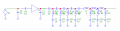
Back to the AB 2, I have tried to trace the schematic and I think I have it down. I know the value of a FEW inductors. Other than that, I only know the range it's supposed to be tuned to. I know on the input side, there are 3 capacitors going to ground with 2 inductors between them, with the inductors in series. The 2nd one is a 1uh. On the output side, there are a TON of series capacitors with inductors going to ground and toward the end a bunch of inductors in series.
Not sure if someone could help with this. My RF knowledge is limited to work I did when I was younger in Ham Radio, I really haven't been in the game in a while. I've not been able to find any schematics on these, it seems they must be locked up at Sennheiser, and these are several generations old units.
I have a Sennheiser AB 2-C antenna booster which is rated for 740-778 Mhz. I would like to use it in the 470-608 spectrum, or even 470-558 range.
I'm not sure exactly the preamp used on this one, it's marked L02. All parts on this model are fixed, the inductors look like a circus.
I also have an AB 3-A amplifier, which is one generation newer which is in the actual range I need, and I notice that those have variable capacitors in those for tuning. The amps used in these cover dc to 6ghz so I know the active components can operate where I need it to.
Back to the AB 2, I have tried to trace the schematic and I think I have it down. I know the value of a FEW inductors. Other than that, I only know the range it's supposed to be tuned to. I know on the input side, there are 3 capacitors going to ground with 2 inductors between them, with the inductors in series. The 2nd one is a 1uh. On the output side, there are a TON of series capacitors with inductors going to ground and toward the end a bunch of inductors in series.
Not sure if someone could help with this. My RF knowledge is limited to work I did when I was younger in Ham Radio, I really haven't been in the game in a while. I've not been able to find any schematics on these, it seems they must be locked up at Sennheiser, and these are several generations old units.