Resonant Frequency

t_n_k

Joined Mar 6, 2009
5,455
Well, the condition we were said by the teacher to look for was when the imaginary part of the circuit impedance was equal to zero.
So, that is what we do and what I have done!
You've missed the point perhaps. You were asking how a simulation in LTSpice could confirm your mathematical derivation. The formula you applied sets the resonance condition - which as you point out renders the parallel circuit to appear devoid of reactive imaginary parts or in other words - purely resistive at resonance. In your simulation you would confirm resonance by noting the source voltage and current being in phase. It remains then to set up a suitable simulation in which you can confirm that result. Comparing the branch currents may not be the most useful approach.
 
Last edited:

ericgibbs

Joined Jan 29, 2010
21,573
hi Psy,

Consider this method of understanding the circuit.

You were asked in the question to show the condition where RC^2 = RL^2 = (L/C)

[My teacher says that if (RL)^2 = (RC)^2=L/C, then the circuit will be at Resonant Point for any frequency..]

Calc the numeric value of L/C, .001/20*10^-6 = 50, The sqrt of 50 = 7.071. So RC=7 and RL=7

Calc the Fres for the parallel circuit without series resistors in the L and C components, you should get 1.125KHz.

Using this Fres calc the ZL and ZC values. which are ZL =~ 7R and ZC =~7R

Fr = 1/2*pi*sqrt(L.C) = 1.125KHz

Calc the 2nd part of the equation. sqrt(( RL^2 - (L/C))/ RC^2 -{L/C)))

sqrt(49-50)/(49-50) = 1

If you now create a LTSpice Sim using L, C and RL = 7R and RC = 7R
[Add the low value R1, this will give a plot of Itotal in the correct sense]

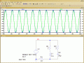
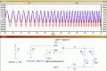
Look at the attached LTS sim, The I total is in Phase with the applied voltage Vs.
[Power Factor of Unity] over a wide range of frequencies.

E

EDIT:
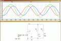
Added image 007, showing the Phases of IL, IC and Itot
 

Attachments

Last edited:

t_n_k

Joined Mar 6, 2009
5,455
Hi Eric,

I suspect the response is so flat owing to the appalling Q. Change the R's to 1Ω each and the response is more like that of a tuned circuit.
 

Thread Starter

PsySc0rpi0n

Joined Mar 4, 2014
1,786
You've missed the point perhaps. You were asking how a simulation in LTSpice could confirm your mathematical derivation. The formula you applied sets the resonance condition - which as you point out renders the parallel circuit to appear devoid of reactive imaginary parts or in other words - purely resistive at resonance. In your simulation you would confirm resonance by noting the source voltage and current being in phase. It remains then to set up a suitable simulation in which you can confirm that result. Comparing the branch currents may not be the most useful approach.
Hum, ok...

So if I plot the Source Voltage and current and check at what frequency they are in phase (where they cross each other), that will give me the Resonant Frequency????

hi Psy,

Consider this method of understanding the circuit.

You were asked in the question to show the condition where RC^2 = RL^2 = (L/C)

[My teacher says that if (RL)^2 = (RC)^2=L/C, then the circuit will be at Resonant Point for any frequency..]

Calc the numeric value of L/C, .001/20*10^-6 = 50, The sqrt of 50 = 7.071. So RC=7 and RL=7

Calc the Fres for the parallel circuit without series resistors in the L and C components, you should get 1.125KHz.

Using this Fres calc the ZL and ZC values. which are ZL =~ 7R and ZC =~7R

Fr = 1/2*pi*sqrt(L.C) = 1.125KHz

Calc the 2nd part of the equation. sqrt(( RL^2 - (L/C))/ RC^2 -{L/C)))

sqrt(49-50)/(49-50) = 1

If you now create a LTSpice Sim using L, C and RL = 7R and RC = 7R
[Add the low value R1, this will give a plot of Itotal in the correct sense]

Look at the attached LTS sim, The I total is in Phase with the applied voltage Vs.
[Power Factor of Unity] over a wide range of frequencies.

E
Hi Sir Eric...

Thanks for your very useful reply. But I'm afraid I'm already in a new question. Not any more about the circuit being at RF for all frequencies... I'm sorry If I confused you once more!

But I appreciate the reply because it was enlightening.

Actually I'm trying to find a way of confirming with LTSpice my calculations for parallel circuits.
 

ericgibbs

Joined Jan 29, 2010
21,573
But I appreciate the reply because it was enlightening.
Actually I'm trying to find a way of confirming with LTSpice my calculations for parallel circuits.
I was answering your previous question, pleased my late post was helpful.
E
 

t_n_k

Joined Mar 6, 2009
5,455
But I think I need to use other kind of simulation rather than AC analysis (Octave) type, right?
Depends on how you do the AC analysis. I don't use LTSpice so I can't offer specific advice. The higher level simulator application I use [SIMetrix] makes the task relatively simple.

However, you might for instance use transient analysis with the source frequency set to your mathematically derived resonance value. Scoping the source voltage and current time varying wave forms should confirm your derived value works.
 

ericgibbs

Joined Jan 29, 2010
21,573
Actually I'm trying to find a way of confirming with LTSpice my calculations for parallel circuits.
hi Psy,
Please post your calcs for the Fres = 1/2pi*sqrt(L/C)* [.......] , lets check your maths.

E
 

Thread Starter

PsySc0rpi0n

Joined Mar 4, 2014
1,786
I was answering your previous question, pleased my late post was helpful.
E
Ah ok... That cleared my doubts about having a circuit at Resonant Point for any frequency!

Can you help me on how to check with LTSpice my calculations for parallel circuits?

Depends on how you do the AC analysis. I don't use LTSpice so I can't offer specific advice. The higher level simulator application I use [SIMetrix] makes the task relatively simple.

However, you might for instance use transient analysis with the source frequency set to your mathematically derived resonance value. Scoping the source voltage and current time varying wave forms should confirm your derived value works.
I'm asking Sir Eric some help for LTSpice advice!

Thanks
 

Thread Starter

PsySc0rpi0n

Joined Mar 4, 2014
1,786
hi Psy,
Post your maths for the equations used and the component values, lets see if its your sums.
E
Ok, the circuit is attached with the L,C, RL and RC values...

We are asked to find the Resonant Frequency.

I've used the following formula:


I got the 722.15Hz Res. Freq.

But I don't really know how check it with LTSpice!
 

Attachments

t_n_k

Joined Mar 6, 2009
5,455
OK - tried LTSpice.

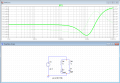
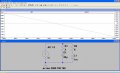
Here's what I obtained using a current source drive with AC analysis. I probed the source current and load voltage. You can hopefully see the signal phases intersect at 0° at the frequency of interest which agrees with your calcs.
 

Attachments

Thread Starter

PsySc0rpi0n

Joined Mar 4, 2014
1,786
OK - tried LTSpice.

Here's what I obtained using a current source drive with AC analysis. I probed the source current and load voltage. You can hopefully see the signal phases intersect at 0° at the frequency of interest which agrees with your calcs.
Ahhhh...

Now I've understood my teacher when he said the when in series we evaluate Voltage and when in parallel we evaluate current!

Big thanks
 

BR-549

Joined Sep 22, 2013
4,928
I am not familiar with the terms you use, but if you are trying to solve for unknown capacitance, there is a easy way to do it. In a series resonate circuit, the reactants are opposite but equal. We know the inductance and the frequency....we can solve for XL = 2xpixFxL. Don't forget to convert mh to H. L must be in henrys. This will give you XL and XL is equal to XC. Now plug XC into XC = 1/2xpixFxC....and solve for C. C will be in farads....convert to mmf. Good luck.
 

Thread Starter

PsySc0rpi0n

Joined Mar 4, 2014
1,786
I am not familiar with the terms you use, but if you are trying to solve for unknown capacitance, there is a easy way to do it. In a series resonate circuit, the reactants are opposite but equal. We know the inductance and the frequency....we can solve for XL = 2xpixFxL. Don't forget to convert mh to H. L must be in henrys. This will give you XL and XL is equal to XC. Now plug XC into XC = 1/2xpixFxC....and solve for C. C will be in farads....convert to mmf. Good luck.
Thanks...

Thanks exactly what we use to do when the circuit is considered to be purely resistive! That's one of the 3 ways Sir Eric told me that we can solve these kind of problems!

Cheers
Psy
 
Top