Facebook
 Google
 GitHub
 Linkedin
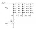
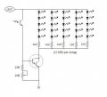
I'm trying to make a flash slave as in the attached diagram. The light source consists of five series of ten bright white LEDs, each series with it's own 100 ohm resistor. The unit works well, although not as bright as flash tube, but good for macro photography. I want it to be triggered by the camera's built in flash, but I can't get it to work satisfactorily. When I shine a torch on the photo resistor, it saturates and the LEDs light up bright, but when I try to activate the system with the flash, the LEDs don't seem to work. The photo transistor is probably an IR type (can't find a visible light one), but I expect a flash tube to emit a broad light spectrum including sufficient IR to saturate the photo transistor. R1 is 100k and R3 is 50k. I've looked on-line and saw some diagrams without an R1 or an R2, but wouldn't that blow the BD649 or the photo transistor when it saturates? Does anyone have any suggestions?
Attachments
-
7.6 KB Views: 26

") )
)