Because I am not smart enough to answer that. All the segments are negatively hooked to an Arduino, positive is common, there are buttons that increase the score and change the numbers. Currently I have one side of the board led's hooked to a 5v port on the Arduino, and the other side hooked to another 5v port on the Arduino.
Newbies often think they can sink/source 40mA on any digital/analog pin. That isn't the case. Devices aren't guaranteed to survive operating at absolute maximum ratings. A more reasonable current would be 20mA.
Additionally, Arduino Uno/Nano have 3 ports and the maximum current per port is 30mA.
Whoever programmed the Arduino for you didn't know what they were doing. They could code, but they don't understand electronics.
How are the 470 ohm resistors wired? Are they between the common anode and the supply?
That's the only way possible. So with a 470 ohm resistor the max current drawn through the entire 25 LED display can only be appx 6ma assuming a 2 volt drop across the LEDs.
Newbies often think they can sink/source 40mA on any digital/analog pin. That isn't the case. Devices aren't guaranteed to survive operating at absolute maximum ratings. A more reasonable current would be 20mA.
Additionally, Arduino Uno/Nano have 3 ports and the maximum current per port is 30mA.
Whoever programmed the Arduino for you didn't know what they were doing. They could code, but they don't understand electronics.
How are the 470 ohm resistors wired? Are they between the common anode and the supply?
Essentially.. 54 leds per 5v port on the Arduino.
I just plugged wires in where I was told, lol.
This is Arduino mega, as there are around 40 connections.
Yes, well He was from Pakistan and he was cheap!
Yes, from each number there is a 470 resistor, and then 4 numbers connect into one 5v supply on the Arduino.
Part of my trouble shooting included using a separate power supply for the leds.. which now I know made no difference because of the resistors. If it is thought that hooking directly to the Arduino will burn it out, that would be another option.
The ATmega1280 has more ports and can handle more current per port, but the per pin limit is the same.
There's a reason why they say "you get what you pay for". If you want cheap, you get cheap.
There really wasn't another way to complete this as I saw. There wasn't a lot of money to be spent, as its for a home game. Only place I could find someone to do the programming was Fiverr for a price that was in the range. You are right though. But, it was this or nothing.
Are any of the digits/segments in parallel? I.e., do they display the same numbers simultaneously?
However, 54 individual segments at 6mA apiece is 324mA. Way over the maximum allowed current draw from a Mega of 200mA. Unless it is powered by the USB port.
Either something is going to break soon, or you need to provide more information
Are any of the digits/segments in parallel? I.e., do they display the same numbers simultaneously? Yes, each side is a duplicate of the other side. So I have a segment from every side going to the same Arduino port. One segment on side A is wired to the same segment on side b to the same port on the Arduino. But, those are negative ports/connections. The way it was designed originally the Positive side of the leds share a common power connection. So I split each side up, so, roughly 100 leds that make up the 4 numbers each with 7 segments for 28 segments a side.
54 individual segments at 6mA apiece is 324mA. Way over the maximum allowed current draw from a Mega of 200mA. Unless it is powered by the USB port.
Either something is going to break soon, or you need to provide more information That's essentially why I came here. If I directly wired the leds, without the Resistors they are plenty bright, but I wondered if it would burn out. I think I can solve that issue with wiring the positive side of the leds to its own power supply. That way the Arduino would not be powering the leds.
(That way the Arduino would not be powering the leds.)
That will not solve the problem because the LEDs are driven by the Arduino. Without some resistors installed both the LEDs and Arduino will be damaged eventually.
(That way the Arduino would not be powering the leds.)
That will not solve the problem because the LEDs are driven by the Arduino. Without some resistors installed both the LEDs and Arduino will be damaged eventually.
Are any of the digits/segments in parallel? I.e., do they display the same numbers simultaneously?
However, 54 individual segments at 6mA apiece is 324mA. Way over the maximum allowed current draw from a Mega of 200mA. Unless it is powered by the USB port. Would a usb cable, usb plug in do the trick? Why is that diffent from the 9v power supply that powers the arduino?
Either something is going to break soon, or you need to provide more information
So is the Arduino providing power for the common anodes?
If you have the code (sketch) and can invert the polarity of the pins driving the LED cathodes, you could have the common anodes connected to the 5V supply and have the Mega drive transistors that sink the LED current.
You could do something like this:
150 ohm resistors would give a maximum current of 20mA through each segment. That would eliminate any problems with a cascading failure caused by an LED hogging more than its maximum continuous current rating because discrete LEDs are usually spec'ed for 20mA continuous. The MOSFETs used are surface mount. You could replace with something like 2N7000 if you can't handle surface mount components; though a logic level device would be better. You could also replace them with a general purpose NPN transistor like 2N3904, but you'd need to add 2k base resistors.
This does nothing to address the unequal brightness for LEDs in a segment.
I'm saying change the 470 ohm resistor to increase the brightness but do not go below 100 ohms. If that's satisfactory your done, otherwise a separate driver circuit is required like in post 13 or 52.
So is the Arduino providing power for the common anodes? This is a little complex for me. Currently I have two wires coming from the arduino 5v ports powering the 200 leds. so, 100 leds per 5v port on the arduino.
If you have the code (sketch) and can invert the polarity of the pins driving the LED cathodes, you could have the common anodes connected to the 5V supply and have the Mega drive transistors that sink the LED current. Yes I have the code. I'm trying to think this through.. after a bourbon or two. My belief is the LED's are positive/negative dependent.. and can't just be swapped so that the Arduino powered each segment positive, and the shared a common negative. My thinking is, I would have to physically switch each of the 210 leds around. Which.. isn't a nice thought. Maybe I am not grasping that correctly though..
You could do something like this: View attachment 256567
150 ohm resistors would give a maximum current of 20mA through each segment. That would eliminate any problems with a cascading failure caused by an LED hogging more than its maximum continuous current rating because discrete LEDs are usually spec'ed for 20mA continuous. The MOSFETs used are surface mount. You could replace with something like 2N7000 if you can't handle surface mount components; though a logic level device would be better. You could also replace them with a general purpose NPN transistor like 2N3904, but you'd need to add 2k base resistors. As far as I know... there aren't any MOSFETS... Unless you're talking about something on the Arduino itself.
This does nothing to address the unequal brightness for LEDs in a segment.
I'm saying change the 470 ohm resistor to increase the brightness but do not go below 100 ohms. If that's satisfactory your done, otherwise a separate driver circuit is required like in post 13 or 52.
That is what I will try, and hope that it is bright enough. currently with the 470 ohm resistors I can not tell a difference in brightness between the segments. So, hoping that continues to a lower ohm resistor.
There weren't any Arduino's in the original design either.
It would be difficult to believe that a company would do something as dodgy as you're trying to do. But they did put LEDs in parallel with no ballast resistors and that's something no reputable EE would do in a finished product.
There weren't any Arduino's in the original design either.
It would be difficult to believe that a company would do something as dodgy as you're trying to do. But they did put LEDs in parallel with no ballast resistors and that's something no reputable EE would do in a finished product.
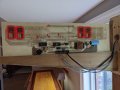
It originally had more 'stuff' on the board. And I undoubtedly could of done something different to make more use of what they had.. but.. here we are. I attached a picture of the original board. I am sure they did not try to do something as dodgy as I am trying to do. Its a learn by mistake kind of game here.
Now we're in the late 70's to early 80's. EPROMs weren't invented until 1971 (by Dov Frohman) and probably another 10 years or so before they had microprocessors with embedded EPROM (MC68705).
If you use the 220 ohm resistors, you’ll be drawing almost twice the current from the Arduino. 650 mA from a source that can only supply 200 mA. The Arduino will quickly fail.
You need to drive each segment with a transistor: a BJT, MOSFET or a ULN2003A. That will only require 1/10th the current from the Arduino. You’ll need one resistor per discrete transistor to set the drive current.
Then, you can increase the current to the LEDs to make them brighter.
Also, you need one resistor per segment, to keep a 1 the same brightness as an 8. At low levels (such as st 6 mA), the differences may not be great. But if you want the LEDs brighter, it will become obvious.
 Facebook
 Google
 GitHub
 Linkedin