Resistor Question

Thread Starter

Ticrandall

Joined Dec 31, 2021
40
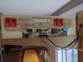
Picture before I did the damage I did. Someone threw a bottle at the board and smashed the IC chip, a display driver. I got a replacement from a really nice guy at the company, however it did not fix the issue. I wanted to use WS2812B led's for the project, but could not find a feasible way to solder them in the close proximately to each other for this project. At that point I elected to try to salvage as much of the original board as possible. Somehow, they had it working with the segmented numbers as they are.
 

Attachments

BobTPH

Joined Jun 5, 2013
8,961
My suggestion requires 16 resistors and 32 connections. You are not going to get an acceptable solution with one resistor per digit.

Bob
 

sghioto

Joined Dec 31, 2017
5,390
The two 470 ohm resistors are connected side by side as in this image. It's equivalent to a 235 ohm resistor. One pair for each LED module.
1640981084976.png
 

Thread Starter

Ticrandall

Joined Dec 31, 2021
40
My suggestion requires 16 resistors and 32 connections. You are not going to get an acceptable solution with one resistor per digit.

Bob
I am not following. There are 8 numbers, 7 segments each, that's 56 segments. Plus the game over/selections lights. If I understand , you said each segment needs a resistor. 56 resistors, 112 solder connections.
 

Thread Starter

Ticrandall

Joined Dec 31, 2021
40
The two 470 ohm resistors are connected side by side as in this image. It's equivalent to a 235 ohm resistor. One pair for each LED module.
View attachment 256545
I can try that. I do have 220 ohm resistors that I can exchange the 470s with. Is there a benefit to doing the 2 470s in parallel over a single 220? The board is at a buddies house. I was tasked with fixing the board.
 

BobTPH

Joined Jun 5, 2013
8,961
Oh, there were only two in your picture. Of course there had to be more.

How are the digits driven? Surely some of the segment wires have to come together somewhere, not 56 outputs from the Arduino, right?

Bob
 

Thread Starter

Ticrandall

Joined Dec 31, 2021
40
Oh, there were only two in your picture. Of course there had to be more.

How are the digits driven? Surely some of the segment wires have to come together somewhere, not 56 outputs from the Arduino, right?

Bob
Its double sided. and... Don't call me surely. Sign is duplicated side for side, so 1 segment is connected to the other corresponding segment on the other side of the board.
 

Attachments

Thread Starter

Ticrandall

Joined Dec 31, 2021
40
Its double sided. and... Don't call me surely. Sign is duplicated side for side, so 1 segment is connected to the other corresponding segment on the other side of the board.
I forget, the issue is, the wires that go to the Arduino are negative. There is only 1 positive per number - 7 segments share the common positive. That's how they did it when it was built. I would have to unsolder every led, and swap them, and then also solder in the resistor. Easier to throw it away and do something smarter.
 

sghioto

Joined Dec 31, 2017
5,390
Going back to post #1 the simplest way to increase the brightness is lowering the resistor values. It's not the best approach but in the end the quickest.
 

Thread Starter

Ticrandall

Joined Dec 31, 2021
40
Going back to post #1 the simplest way to increase the brightness is lowering the resistor values. It's not the best approach but in the end the quickest.
That is what I will try. Someone suggested a 5 band 220, I have a 4 band 220.. That still work?
 

Thread Starter

Ticrandall

Joined Dec 31, 2021
40
You haven't given us any information regarding how the LEDs are being driven.
Because I am not smart enough to answer that. All the segments are negatively hooked to an Arduino, positive is common, there are buttons that increase the score and change the numbers. Currently I have one side of the board led's hooked to a 5v port on the Arduino, and the other side hooked to another 5v port on the Arduino.
 
Top