Replacing star delta motor starter with Variable frequency drive

If you had a open circuit to the slip rings, the motor current would be almost nil, and the rotor would remain stationary.
You increase torque by decreasing resistance.
Max.

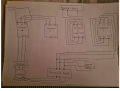
A wound-rotor motor, also known as slip ring-rotor motor, is a type of induction motor where the rotor windings are connected through slip rings to external resistance. ... When the motor reaches full speed the rotor poles are switched to short circuit. During start-up the resistors reduce the field strength at the stator.
I thought the idea was to bring the rotor's power factor closer to unity during startup rather than having any sort of impact whatsoever on the stator field.

More resistance -> less inductive reactance -> better rotor power factor -> more forward torque and less backwards torque. À la NEMA 'A' vs NEMA 'D'.

https://www.elprocus.com/what-is-slip-ring-induction-motor-and-its-working/
 
Last edited:

MaxHeadRoom

Joined Jul 18, 2013
30,677
The optimum torque in induction motor is when the rotor contains a shorted turn, if you increase the winding's, current decreases and the torque reduces, in the case of a wound rotor motor using a variable resistance, the torque
I thought the idea was to bring the rotor's power factor closer to unity during startup rather than having any sort of impact whatsoever on the stator field.

More resistance -> less inductive reactance -> better rotor power factor -> more forward torque and less backwards torque. À la NEMA 'A' vs NEMA 'D'.
That is basically true, but Both a wound-rotor induction motor with all of the resistance cut out of the speed controller and a squirrel-cage induction motor show nearly the same efficiency performance. However, when a wound rotor motor must operate at slow speeds with all of the resistance cut in the rotor circuit, the efficiency of the motor is poor because of the power loss in watts in the resistors of the speed controller.
Here is also a good link description, https://www.industrial-electronics.com/elecy4_17.html
 

Thread Starter

mztrordinary

Joined May 25, 2016
54
Hi guys thanks for all the support. After talking to my motor rewind guy he highly recommends that I do not put an inverter on it but just upgrade the switchgear to new. So i have attached a hand drawn sketch of the contactor set up which to me isnt the usual star delta which i am familiar with.

The first contactor as you can see is wired back around on itself. It then has 3 wires coming from L1 L2 L3 down to a terminal block which is then running 3 of the 6 phases to the motor. Also connected to the L1 L2 and L3 terminals is 3 wires which run back up to the resistor bank on top of the panel.

The second contactor which also has a timer on it again is wired back onto itself and has another 3 wires on L1 L2 and L3 going back up to the same resistor bank on the top of the panel.

The third contactor is wired to the 4th contactor with L1 L2 and L3 but it has nothing connected to its output/load side and upon watching the machine run it doesnt do anything.

The fourth contactor is the one with the overload and is taking 2 phases L1 and L3 from the 3 phase supply into the panel. It then goes to the overload and then out to the motor with the other 3 phases. Just not really familiar with this set up so wondering if you were?
 

Attachments

MaxHeadRoom

Joined Jul 18, 2013
30,677
That diagram appears to be incomplete, also apparent errors?
Is, or was the original object to have 3 stepped speeds?
Do you have the original schematic of the machine?
Max.
 

Thread Starter

mztrordinary

Joined May 25, 2016
54
Hi Max
No there is no schematic for it this machine is very old and has been in a couple of different places. attached is a photo i took just before leaving i will not be able to get back to this until monday. The four contactors from the drawing are in the image starting from right to left. The small timer unit is just an interlock so i am not too worried about that. As you can see the third contactor in is the one which isnt connected to any output and the fourth one is the run contactor with overload
 

Attachments

Opening up that picture is certainly an "oh boy" moment. What a mess. A guy could spend two or three hours just tracing out wires in that rat's nest. Terminal blocks floating willy-nilly in space, power conductors running kiddywompus across the tops of the contactors, almost no color-coding... no workmanship at all. "Get it working then shut the door". Shameful.

I'd double check the connections on your diagram because as-drawn contactors 1, 2 and 3 comprise expensive and complicated do-nothing apparatus. There's no doubt this cabinet has seen a few alterations in it's time. The best advice I can give you is don't trust the last guy's work.
 
Last edited:

Thread Starter

mztrordinary

Joined May 25, 2016
54
Opening up that picture is certainly an "oh boy" moment. What a mess. A guy could spend two or three hours just tracing out wires in that rat's nest. Terminal blocks floating willy-nilly in space, power conductors running kiddywompus across the tops of the contactors, almost no color-coding... no workmanship at all. "Get it working then shut the door". Shameful.

I'd double check the connections on your diagram because as-drawn contactors 1, 2 and 3 comprise expensive and complicated do-nothing apparatus. There's no doubt this cabinet has seen a few alterations in it's time. The best advice I can give you is don't trust the last guy's work.
Yeah I agree 100% its poor that is only one panel of 2 the other one is just as bad and contains a barely working PLC and same rats nest of wires. I will be building a whole new panel with HMI and PLC proper wiring and schematic. I was starting on the larger panel with wire tracing but can only do it at certain times after hours and even them I am limited because I can only stay for certain amount of time before building closes.
Its a big job but one i want to take on as like you said shameful work like that should not be in a place of production.
 

MaxHeadRoom

Joined Jul 18, 2013
30,677
In light of the pic's etc and the age, I would be tempted to either gut it and start over, or just start afresh with a new enclosure if necessary.
Use a decent wiring technique C/W wire duct & labeling etc.
Plus a decent schematic for future trouble-shooting. Probabally just as expedient.
Max.
 
Last edited:

Thread Starter

mztrordinary

Joined May 25, 2016
54
In light of the pic's etc and the age, I would be tempted to either gut in and start over, or just start afresh with a new enclosure if necessary.
Use a decent wiring technique C/W wire duct & labeling etc.
Plus a decent schematic for future trouble-shooting. Probabally just as expedient.
Max.
Yes I agree 100% I will build a new panel offline and test it before gutting the existing one and replace it over a weekend. While we are on the subject does the hand drawn circuit i posted a while back even look somewhat similar to slip ring motor starting? I have been browsing the web for schematics and images but not really fruitful at the moment unless anyone has any tips


Although i did find this

1613773357888.png
 
Last edited:

MaxHeadRoom

Joined Jul 18, 2013
30,677
Details of exactly what the motor duties are, are needed?
What is the mechanism and function of the motor?
Appears to be a 3 step speed function?
For panel building details, look up a copy of NFPA79, there is a copy out there in PDF.
Max.
 
Just thinking aloud here - I don't see a rectifier in your picture and guessing purely based off of the patterns of the leads and heat sinks on the resistor bank it looks like it might be set up in a two-stage star connection? Not sure if they're using it for speed control at all or purely starting purposes. Would be interesting to see if those two timers are set up to cascade two contactors. Not sure why they're red - that color usually denotes a safety relay. Coils might be wired in series with some E-stops somewhere?
 
Last edited:

MaxHeadRoom

Joined Jul 18, 2013
30,677
I'm guessing it has three resistor-set speeds for three functions, connected via the 3 phase brush output with contactors either picking up in sequence or as required by some type of controller.
As per the DWG.
If a bridge had been fitted, it would have just eliminated one resistor in each bank.
Max.
 

Thread Starter

mztrordinary

Joined May 25, 2016
54
No there is no rectifier or speed control. There is a variator fitted between the motor and gearbox but that hasn't been touched in years its one speed fits all. I just wasn't sure about the power wiring at first until I looked into it. Like my rewind guy said just replace like for like with the switchgear with newer and leave the motor as although they are very old type and rare these days they are still a great unit of a motor like you guys said I will have to spend hours in the panel tracing wires before I can come up with proper layout and start building while new panel offline. I plan to disconnect the motor from the circuit and run the contactors and take times and see what is switching in and out that alone will take a couple of days
 

MaxHeadRoom

Joined Jul 18, 2013
30,677
I just wasn't sure about the power wiring at first until I looked into it. Like my rewind guy said just replace like for like with the switchgear with newer and leave the motor as although they are very old type and rare these days they are still a great unit
Yes, unless it is documented, you would need to study the timing/sequence for the operation of the three contactors, and the various machine sequence it coincides with.
I don't think you have yet mentioned what type of mechanism/machine it is involved with?
 
Top