Replacement for a OLD STR (Sony CRT)

Thread Starter

ranatungawk

Joined Oct 30, 2008
212
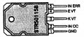
I found this STR (50115B) in a Old Sony CRT TV. Can yo please suggest me a matching one ? Meanwhile can we test a STR with a multimeter ?
 

Thread Starter

ranatungawk

Joined Oct 30, 2008
212
I don't think there is a replacement it's obsolete, you can test it, it's just three transistors in a package. Picture bottom left.
Thanks !

According to the diagram, one inside transistor can be isolated and checked through Pin 2-3-4. I set the DMM for 2000K scale and tested all combinations. Then the same test was done setting the multimeter for diode section too. At both tries I got "no readings" for any kind of combination. Does that mean this STR fail?
 

MisterBill2

Joined Jan 23, 2018
27,164
At least here in the USA the change to digital television made every one of the previous 50 years models obsolete, as in not being able to display the new broadcast format. A brilliant move to promote the sales of new products.
It nay be simple to replace the function of that device with several devices combined, or the TS may need to design a whole new circuit. But what is the value of an obsolete CRT television??
 

Thread Starter

ranatungawk

Joined Oct 30, 2008
212
At least here in the USA the change to digital television made every one of the previous 50 years models obsolete, as in not being able to display the new broadcast format. A brilliant move to promote the sales of new products.
It nay be simple to replace the function of that device with several devices combined, or the TS may need to design a whole new circuit. But what is the value of an obsolete CRT television??
A hobbyist's attempt to demonstrate enthusiasm. :)
 

R!f@@

Joined Apr 2, 2009
10,004
You know I used to repair the tubes in the old days, When I cannot get an STR, or anything of the sort with just transistors inside, I would just use appropriate transistors. Of course data helps. If cooling is good then it holds. It will hold till I can source the part at least.
 

Dodgydave

Joined Jun 22, 2012
11,395
Thanks !

According to the diagram, one inside transistor can be isolated and checked through Pin 2-3-4. I set the DMM for 2000K scale and tested all combinations. Then the same test was done setting the multimeter for diode section too. At both tries I got "no readings" for any kind of combination. Does that mean this STR fail?
I always check transistors on Diode function, it puts out a 2V test, so a good transistor measures 0.7V, across B/E,,and open circuit across C/E terminals
 

MisterBill2

Joined Jan 23, 2018
27,164
Certainly the device function can be duplicated with a number of external components, and for a hobby application that makes sense. And, in fact, that will be an interesting and educational process. My comment was based on the application for the repaired TV in my area, I had neglected to consider that in other areas it may still be useful.
 

Thread Starter

ranatungawk

Joined Oct 30, 2008
212
I went and looked; I do not have one. I worked for Sony for years. Why do you think this part is bad?
A part of the circuit is attached herewith. Could you please help me to locate the issue ?. When power is ON , the voltage of the main cap (C606) goes to 330V. then through the primary winding of the chopper 320V appear on the 3rd pin (input) of the STR. However, no voltage (as it mentioned: 116V at pin 2 and the B+ 115V at pin 4) appears on other pins. Further, H-OUT and the surrounding components in the power supply were cached and found OK.
 

Attachments

MisterBill2

Joined Jan 23, 2018
27,164
The lack of the 115 volt output might also be caused by a lack of base drive to the pass transistor. BUT, as happens in many posts, we can not see enough of the circuit to even suggest a possible cause. But in this case, a short circuited capacitor, C621, would prevent any base drive. Has the voltage at that pin of the questioned device been checked??
Very often, understanding how a circuit functions can be of great value in locating the cause of incorrect function.
Usually that works much better than just checking for failed components.
So please show us more of the circuit that drives the base of that pass transistor.
 

Thread Starter

ranatungawk

Joined Oct 30, 2008
212
The lack of the 115 volt output might also be caused by a lack of base drive to the pass transistor. BUT, as happens in many posts, we can not see enough of the circuit to even suggest a possible cause. But in this case, a short circuited capacitor, C621, would prevent any base drive. Has the voltage at that pin of the questioned device been checked??
Very often, understanding how a circuit functions can be of great value in locating the cause of incorrect function.
Usually that works much better than just checking for failed components.
So please show us more of the circuit that drives the base of that pass transistor.

Thanks for the information. as requested , the complete diagram is attached herewith.
 

Attachments

MisterBill2

Joined Jan 23, 2018
27,164
OK, now it is clear that the IC/module is the sole active component in a self oscillating power supply. The news is that quite a few of the components attached to that transformer could also prevent oscillation that would produce the 115 volts and the other voltages.
In addition, there could be a shorted component causing that module to fail.
So it may be possible to duplicate the functionality of that device with a circuit built up to replace that device.
So the challenging part will be to locate the information to be able to duplicate the functionality.

Not only that transformer, but also another transformer, are driven by that one module. It took examining the whole circuit drawing to see what was happening.
 

crutschow

Joined Mar 14, 2008
38,316
At least here in the USA the change to digital television made every one of the previous 50 years models obsolete, as in not being able to display the new broadcast format. A brilliant move to promote the sales of new products.
So you really think that's the reason transmission of the old NTSC Standard Def analog signal was terminated, even though adapters were given away to allow reception of the digital signal on the old analog sets? :rolleyes:
 

MisterBill2

Joined Jan 23, 2018
27,164
So you really think that's the reason transmission of the old NTSC Standard Def analog signal was terminated, even though adapters were given away to allow reception of the digital signal on the old analog sets? :rolleyes:
Certainly the primary motivation for the change was to increase profits. That is how business operates. And certainly the ability do deliver higher resolution boosted sales. And just as certainly the distribution of the converters provided a less satisfactory means of TV reception. And there was a whole decade or two, or three, of television receivers that had neither video input connectors nor an "F" connector for an antenna input. And the little adapters would confuse a lot of folks.

I did connect a few of them for folks who were technically incompetent to follow those quite well presented instructions,
It is truly amazing the number of folks who have no concept of how to mate an "F" connector pair correctly.
 

Thread Starter

ranatungawk

Joined Oct 30, 2008
212
Thanks for the information. The fault was in the STR! By replacing it with a new one, the power came back. These old STRs should be checked at meg-ohm range; at the diode testing scale, they show no readings.
 

bassbindevil

Joined Jan 23, 2014
918
But what is the value of an obsolete CRT television??
There's a growing number of folks who want to experience 1980s and 1990s game consoles on a CRT display. And retro computing enthusiasts who would pay actual money for those CRT monitors and old Gateways you dumped at the recycling yard last week.
 

MisterBill2

Joined Jan 23, 2018
27,164
I did not dump them. I sold them at a swap for a fairly low price. I am done with them and they went to somebody who wanted them enough to pay more than the scrap value. That was my choice, I am happy with it.
 
Top